


A heating, ventilation and air-conditioning (HVAC) piping system is designed to convey a heat transfer fluid to multiple air handlers, providing cooling (chilled water) or heating (hydronic heating) loads in a building. A typical HVAC system consists of a primary loop and a secondary loop. The primary loop contains the chiller or boiler along with primary circulating pump(s). The secondary loop draws fluid from the primary loop and consists of a secondary pump along with the supply header piping, various air handlers and return-header piping. The primary and secondary loops are connected, so fluid mixes between the loops.
The key to designing an HVAC circulating water system is to control the air handling flow rates to maintain the temperature in the conditioned spaces. There are two methods to achieve this goal; one is a constant volume system, the other a variable demand system. Below is a case study of how a project in the Pacific Northwest achieved cost savings by using a variable demand system versus a constant volume system.
Modeling the System
Before you design a new system, or make major modifications to an existing piping system, it is a good idea to create a computerized hydraulic model of the HVAC piping system. Piping software can provide the information needed to properly select the pumps and control valves. The model also provides a good understanding of the interaction of pumps, pipelines and control valves.
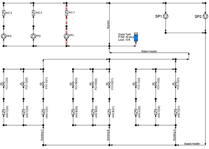 Image 1. Modeled HVAC system (Images courtesy of the author)
The information from the computerized model can also be used to perform an economic analysis of pumping costs for both types of control systems. Image 1 is a rendering of a modeled HVAC system.
To perform this analysis, look at the differences between constant volume control and variable demand control, and perform a pumping cost analysis for each.
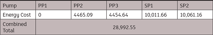 Image 2. Yearly operating cost calculator results: constant volume
Constant Volume Control vs. Variable Demand Control
Under constant volume control for the piping layout in Image 1, both secondary pumps are operating just over 660 gallons per minute (gpm). Since this is a constant volume system, both pumps will run constantly at this flow rate year-round. To keep the volume constant, some flow will go through the air handlers, and the remainder will go through a bypass line.
In a variable demand system, the flow rates to the loads vary based on the required heating or cooling needs. The first requirement is to estimate the required flow rates. They are based on the heating or air conditioning loads and may vary by the time of year and time of day.
In this analysis, it has been assumed that the average flow requirements in the winter months will be 30 percent of the maximum design flow, spring and fall is 45 percent of the maximum, and in the summer the design flow is 85 percent of the maximum. Note that the maximum design load is based on the needs for the hottest or coldest day of the year.
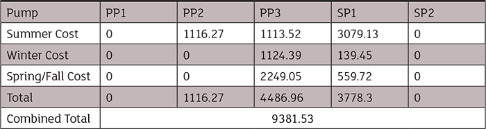 Image 3. Yearly operating cost calculator results: variable demand
Constant Volume Pumping Costs
For this project, the yearly pumping costs for the system were an energy rate of 8 cents per kilowatt hour (kWh). This should provide a conservative estimate of costs elsewhere as the national average is close to 13 cents per kWh. The operating costs for pumps SP1 and SP2 are $10,012 and $10,062. Together, the operating cost for the secondary pumps at a constant volume and fixed speed is $20,074.
Variable Demand Pumping Costs
The variable demand costs are slightly more complicated as the loads vary more throughout the year. Here, we are using the flow rates mentioned above and considering summer, winter, spring and fall to each account for 25 percent of the year. The spring and fall demands are the same so they have been combined for a total of 50 percent of the year.
The system is capable of meeting the demands year-round using only one secondary pump. The operating costs for this secondary pump are $3,080 in the summer, $140 in the winter and $560 in the combined spring and fall seasons for a total of $3,780 for the year.
The annual operating cost for the secondary pumps is less than the cost associated with the constant demand system. The reduction in cost can be brought about by installing a variable frequency drive (VFD). It is important to factor in the cost of the VFD in your life cycle pumping cost calculations.
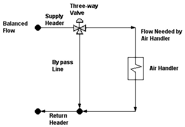 Image 4. Typical constant volume circuit
Constant Volume System
The constant volume system is such that a constant volume of fluid is flowing to each air handler regardless of the load. The piping to the air handler consists of a three-way valve that directs flow to the air handler or to a bypass line (Image 4).
In a constant volume system, the combined flow in the bypass line and to the air handler is constant, regardless of the flow rate to the air handler. A three-way valve directs the fluid through the bypass line, unless there is a demand on the air handler. When a demand is placed on the air handler, the three-way valve is repositioned to send some fluid to the air handler and less fluid through the bypass line. When there is no longer a demand by the air handler, the valve redirects the flow through the bypass line.
The major advantage of the constant volume design is that once the system is balanced, by setting the design flow rate to each load, the control system is stable. The three-way valve is able to direct the flow to the air handler without affecting the total flow rate through the system.
The disadvantage to the constant volume system is the flow rates to each air handler are the same year-round regardless of the system’s heating or cooling load. In other words, in an HVAC chilled water system, the flow rate through the secondary loop is the same for the coldest day of winter as it is for the hottest day of summer. Therefore, constant volume systems typically incur a higher operating cost because the flow rate through the secondary system is the same regardless of the system load.
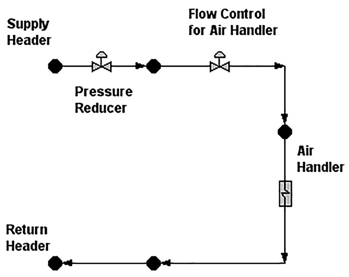 Image 5. Typical variable demand circuit
Variable Demand System
Now that energy costs are higher, variable demand systems are becoming more popular. On a variable demand system, the three-way valve and bypass line are replaced with a pressure reducer and control valve in series to regulate flow to the air handler (Image 5). As the control valves in the other loads regulate the flow rate, the differential pressures across the control valve can vary. The wide variation of differential pressure across the control valves due to changes in system loads could cause problems with the control valve.
To overcome this problem, a pressure regulator is placed upstream of the flow control valve to absorb some excess differential pressure between the supply header and return header. The job of the pressure regulator is to reduce the pressure drop across the control valve. A smaller valve actuator can then be used so a finer control can be achieved.
Using a variable demand system saves on the operating cost, because the flow rate through the system varies to meet the needs of the system demands rather than maintaining a constant system flow rate.
Greater cost savings can be achieved on a variable demand system by adding a VFD. As mentioned previously, a pressure regulator is typically placed upstream of the control valve to limit the maximum differential pressure across the control valve. As the flow rates in the other paths decrease, the pump moves back on its pump curve and provides a greater differential pressure across the pump. This results in a greater differential pressure across the supply and return headers. The job of the pressure regulator is to absorb some of the excess differential pressure so the control valve can operate properly.
By installing a variable speed drive (VSD) and controlling the pump’s speed based on the differential pressure across the various control valves, the pump produces less head for the same flow rate. This results in a lower differential pressure across the pressure regulator. Since the pump head is less, the pump consumes less energy, resulting in further savings.
There needs to be a minimum differential pressure across each control valve for the valve to operate properly. The purpose of the VSD is to slow down the pump to provide only sufficient head needed for the control valves to operate properly. There is usually one control valve in the system that has the lowest differential pressure, and this is referred to as the most hydraulically remote control valve. A differential pressure sensor can be installed across the most hydraulically remote control valve to control the pump speed.
Conclusion
Based on the various load combinations to the air handlers, the most hydraulically remote control valve in the system can change. Therefore, additional differential pressure sensors may be needed, resulting in additional instrumentation.
There may be many loads in a large HVAC system, so it can become cost-prohibitive to insert differential pressure instrumentation on each control valve. It can be more cost-effective to install the differential pressure controls only on the valves that may face the lowest pressure drop. This requires a thorough understanding of the HVAC piping system.