


“If the only tool you have is a hammer, everything starts to look like a nail”… paraphrased from Dr. Abraham Maslow (“Psychology of Science,” 1966). This famous axiom is also referred to as the law of the instrument. To explain further: once we learn a new skill or how to use a new tool, we begin to see new opportunities for its use everywhere we look, but at the same time we also often forget about all the other instruments in the toolbox.
Suction specific speed (NSS) can be thought of as one index or tool in a mix of several tools regarding impeller design. NSS is a dimensionless parameter that describes the relationship between the speed, the flow rate and the net positive suction head required (NPSHr) of the rotating impeller. NSS is a tool, and it is not really a “speed” or “speed limit” at all.
The concept of NSS was developed in the late 1930s by Igor Karassik and two associates. By the late 1970s and early 1980s, NSS had become a commonly used tool, ostensibly for predicting hydrodynamic instability in pump operations.
Many people incorrectly view NSS as an absolute “speed limit” posted by the “pump police” in the range of 11,000 (no units). However, to paraphrase the respected comments of professional engineer Jerry Hallam, it may be more correct to think of NSS simply as the dashed centerline painted on a two-lane highway … “one can cross the line if proper attention is paid to details.” That is, you need to check for oncoming traffic before you go left of center to pass.
Suction Specific Speed
Over the last few years, I have witnessed a marked increase in the usage of NSS indices in request for quotation data sheets and pump engineering specifications crossing my desk. More often, the entity has little idea what NSS really means or the significance of the number. When I probe for how the end user or their engineer will use and evaluate the NSS data, I typically receive no answer and/or what I perceive as a misunderstanding. The intent of my query to the requesting party is to determine their assigned priority and weight of the NSS number in the overall pump evaluation process, especially when compared to other parameters such as efficiency, NPSH margin and proximity to best efficiency point (BEP).
Note: Please realize there are plenty of people in the industry who fully understand the NSS concept and possess valid reasons for asking the question.
This article is simply a refresher for those people.
Let us revisit the NSS concept. It is not my intent to make this month’s article a primer on NSS, but perhaps to shed new light on a subject that in my experience is commonly misunderstood.
NSS is not to be confused with its older brother and more common concept of specific speed (NS). NS is an indicator of the impeller geometry and discharge characteristics, while NSS is an indicator of impeller inlet geometry and suction characteristics. NSS is, in essence, a function proportional to the speed, pump flow rate and the NPSHr. Visualize NSS as a mathematical expression for the geometric dimensions, spatial arrangement and vane angles at the eye of the impeller. Used properly, NSS can be a reliable harbinger, exploring the possibility of potential pump performance issues.
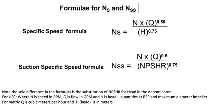 Image 1. The formulas for the calculations of NS and NSS (Images courtesy of the author)
More Rules & Formulas
The formulas for the calculation of NS and NSS are shown in Image 1. The only real difference is that NPSHr is substituted for head (H) in the denominator. If you are not familiar with fractional exponents, there are several NSS calculators on the internet that will do the work for you.
Actually, the pump manufacturer should be able to advise the NSS for all of the impellers they provide.
However, when calculating NSS on your own, look at the manufacturer’s published performance curve for the pump; NSS is based on the flow rate for the maximum diameter impeller at the BEP and the corresponding NPSHr for that same point.
The NSS formula is for single suction pumps (impeller with one eye). Consequently, if the pump is a double suction design (two eyes) like many horizontal split case pumps, then the BEP flow rate for the calculation is simply split in half. For multistage pumps, it is the first stage flow and NPSHr.
Background
Back in the 1970s, new plants and refineries were designed with an increasing strict mandate to save money (sometimes over reliability), especially on the initial construction and material costs. As a cost-cutting measure, the NPSH available (NPSHa) of these systems was reduced (think smaller and lower elevation of tanks, columns and towers and also placing pumps at higher levels). The system owners or pump buyers subsequently placed increasing pressure on the pump manufacturers to design pumps with lower NPSH requirements. I remember when even a 1-foot margin over a competitor would “get the order.”
The simplest and quickest solution for pump manufacturers was to increase the size of the impeller eye. The good news was that the NPSHr was reduced, but the bad news and unintended consequence was the hydraulic stability of the pump was markedly reduced as the operating point moved away from BEP even in small proportions.
In 1979, Hallam was a mechanical engineer with a refinery. The refinery was experiencing serious pump issues of hydrodynamic instability and consequential fires. The fires were mostly a result of mechanical seal and bearing failures.
Hallam was tasked by management with determining the root cause. He and his associates combed through five years of maintenance and operational records and conducted performance tests to collect data on 235 pumps to look for trends and potential causes. For one of the parameters, they calculated and categorized the NSS of each pump, not because they thought this index was the issue, but solely as another piece of data to help find the illusive needle in the haystack. What the data analysis highlighted in the initial results was clear. Data pointed to the fact that the higher the NSS index, the more likely there was an issue for the pump. It was close to a factor of two times more likely.
The research team shared the results with some industry experts and senior management. Hallam and his team were subsequently persuaded to expand the research from 235 to 480 pumps and to include a differentiation of the power levels with 75 horsepower (hp) being a dividing line (this did not make any difference). They also performed a more thorough investigation where each pump operated on its curve and the proximity to the design BEP.
Note, in a refinery environment it is difficult to operate the pumps at their “sold for” condition point. They do, however, operate in a range, and that information was recorded. After all the secondary tests and data were analyzed, the information still pointed to almost exactly what the initial data had spotlighted. In essence, the lower the NSS, the higher the reliability of the machine. Pumps with a low NSS index could be operated more reliably over a wider range. Pumps with high NSS indices that operated in a range at or near BEP were reliable in general. Pumps with NSS at or near 11,000 that were operated away from BEP were more likely to fail.
It is important to note that the pump data perused for the research represented more than 15 million operating hours. While this research was not 100 percent scientific in its methods and analysis, it still remains one of the most exhaustive tasks of data collection and analysis I am aware of in the pump industry.
The previously mentioned hydraulic instability that creates these pump issues manifests as a form of cavitation. Not cavitation in the classical sense of insufficient NPSHa, but cavitation due to recirculation issues inside the impeller.
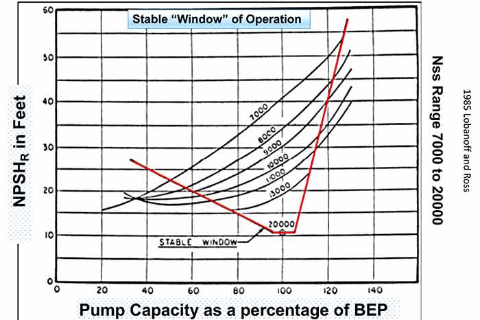 Image 2. Commonly referred to as the “safe operating window”
At the higher NSS index numbers the eye of the impeller is much bigger than on an impeller of the same size (outside diameter), but with a lower NSS. When the pump is operating back (to the left) on its curve, the flow stream in the impeller begins to recirculate because the required flow angles are now changed. The resultant recirculation creates flow separation and higher velocities that reduce the local pressure. If the local pressure drops below the vapor pressure for the liquid, it can lead to cavitation, noise and consequential vibration.
Operation away from the BEP region contributes to some degree for potential shaft deflection and mechanical seal failure, but that is not the focus of this article. One of the results from this NSS research is a commonly referenced chart that is referred to as the “safe operating window” (Image 2).
Another of the offshoots of this NSS and other research is a pump reliability curve often used in pump articles and lectures, but rarely credited to the two people whose idea it was—Ed Nelson and Paul Barringer.
See Image 3 for my modified version of the Nelson-Barringer pump reliability curve.
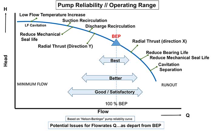 Image 3. Elsey’s modified version of the Nelson-Barringer pump reliability curve
Comments & Cautionary Results
NSS can be used as a prediction tool for cavitation issues. Because NSS is defined only at BEP for the maximum diameter impeller, it is a relative term and should not be considered solely by itself, but in conjunction with the pump operating point on the curve relative to BEP.
Technically speaking, when NSS is computed in U.S. customary units (USC), it is not truly a dimensionless number, and the units do not cancel out. This discrepancy is acknowledged, understood and accepted by most pump engineers and technical subject experts.
The truly dimensionless formula would include the gravitational constant and the rotation would likely be in radians per second.
The more important point is to use consistent units. For USC calculations, also known as the customary or universal version, use gallons per minute (gmp) for flow rate (Q), revolutions per minute (rpm) for speed (N) and feet for NPSHr. For metric use, the flow would be cubic meters per hour and the NPSHr head would be in meters.
Values of NSS for most commercially available impellers vary from approximately 6,000 to 15,000, but can be as high as 18,000 to 20,000 for highly engineered and specialized designs.
Of special interest is the subject of aircraft fuel pumps, which can reach an NSS index of 40,000. Note that many boiler feed and condensate pump designs are in the range of 12,000 to 17,500 because of the unique requirements of the service. In these cases of high NSS, frequently the inlet flow angle on the first stage impeller is reduced and the thickness of the vanes and the number of vanes is also decreased.
When looking at applications with higher NSS indices, consider the following in addition to the index:
- Where will the pump be operated on its curve relative to BEP? The further away from BEP, the more the concern for unstable ops is valid.
- The NPSH margin. As the margin increases the concern for unstable ops can be reduced.
- As the suction energy (SE) increases the concern for stable operations grows.
- The suction velocity and velocity profile and/or how much straight unobstructed suction piping? The lower the velocity and the less turbulent the flow, the better for stable ops as you approach higher values of NSS.
- Perhaps variable speed or a system bypass control will allow the pump to remain in a more stable region.
The NSS “speed limit” placed on pumps was based on impeller designs from the 1960s and subsequent modifications and revisions placed in service in the ’70s and ’80s. Today’s modern and improved impeller designs using updated experience, knowledge and computer assisted modeling data can mitigate and even preclude many if not most of the previous instability issues due to redesigned impeller blades and their respective geometry.
NSS remains a tool to help you make decisions. Perhaps while caution is the prudent choice when approaching 11,000, there are other aspects to consider, like the total installed cost of the system. Work with the pump supplier to define and validate the safe and reliable operating region. It is not a speed limit. It is a caution sign.
References
1. Technical paper (published April 1982 Hydrocarbon Processing), Jerry Hallam, P.E.
2. Pumps and Systems, 2011 series of articles on this subject, Terry Henshaw
3. Centrifugal Pumps, Johann Friedrich Gulich