


When many of us problem-solve, often we focus too closely on the issue as presented, or we try to optimize the performance of a particular pumping system as it is designed in an ideal state. We may fail to fully understand how that system is optimally used in the actual, real-world operation of the facility where it is installed. What’s more, we may unintentionally not identify underlying conditions that, if intelligently confronted, can result in significant savings or performance improvements.
This simple fact came to mind last month, when I wrote about the Canadian nickel mine and processing mill that met demand for greater makeup water flow while controlling electrical costs and maximizing system uptime. You may recall the “loose end” that I referred to: the new makeup water system produced 240 gallons per minute (gpm) of bypass water. What happens to the excess water?
The simple answer was that it was pumped right back to the water’s source, a local river. But the mill wanted to truly optimize the system’s performance as it was actually used. By working in concert with engineering and operations personnel, the plant engineer came to a fuller understanding of what bypass control actually costs each year. The mill then discovered an opportunity to save money while reducing wear and tear on the system and reducing its consumption of water treatment chemicals.
Let’s pick up the story of this “second look” at the mill’s makeup water system.
The Background
All piping systems consist of pump, process and control elements that work together to make a product or provide a service. When all elements work in harmony, the result is increased system uptime, and reduced capital, operations and maintenance costs.
Last month, we discussed that by adding a 20-inch-diameter parallel pipeline to the process element, the existing 12-inch makeup water supply header, the mine could meet its increased flow requirement without incurring the major expense of replacing the existing pump elements.
It also could remove five stages from the vertical turbine pumps. This resulted in a flow rate of 4,740 gpm and saved $969,144 in electrical costs.
Since the requirement was only 4,500 gpm, the new makeup water system produced an excess of 240 gpm. Bypass control back to the river represents 5 percent of the total pumping capacity, which directly equates to 5 percent of the pumping cost of the system.
The plant engineer wanted to know the cost of the controlling system. The journey resulted in an annual saving of $144,000 in operating costs and other benefits. How did the engineer get there?
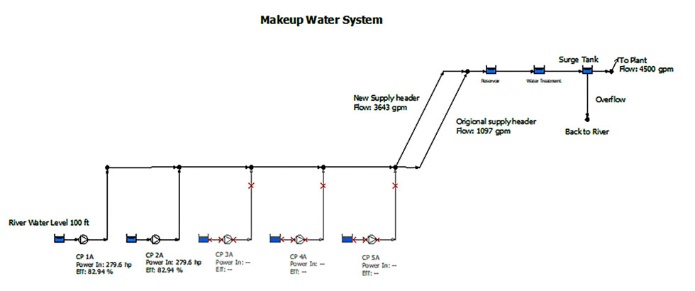 Image 1. The makeup water system showing the bypass control from the surge tank back to the river. (Images courtesy of the author)
Step 1: Finding Actual Needs & Real Costs
The first step was to walk through the makeup water system to understand how things worked. The makeup water was pumped from the river to a reservoir, through a water treatment system, then to a surge tank providing service water to the facility (see Image 1). The bypass control line was connected from the surge tank, with excess water directed back to the river. But upon visually inspecting the surge tank overflow, the plant engineer realized that the flow rate appeared to be much greater than 240 gpm.
The design flow rate of 4,500 gpm was based on the facility’s maximum production capacity. However, the engineer learned that the mill had been operating five days a week at 90 percent capacity for more than a year. As a result, it actually needed only 4,050 gpm of makeup water. Furthermore, the makeup water pumps operated line 24/7 to minimize the number of pump starts. That meant that 4,740 gpm flowed through the bypass control each weekend when the mill shut down on Saturdays and Sundays.
The utility engineer reported that the cost of electrical power was $0.10/kilowatt hour (kWh) and the electrical engineer calculated that the system’s pump motors were 95 percent efficient at the specified load. This information, along with accounting for the mill’s 50-week operating year and the system’s actual 90 percent capacity, drove the creation of a power cost balance sheet (see Image 2).
You can see that it cost $369,429.23 to operate the makeup water pump elements for a year. Based on the operational requirement and the schedule, the process elements consume $225,465.40 to supply the mill with makeup water. The remaining $143,963.83 is consumed by the control element in the form of the bypass back to the river.
Knowing the cost for each element presented a clear picture of system operation, along with a more effective way of evaluating proposed system improvements. In this example, it became clear that shutting down the makeup water pumps on weekends could save $105,551.21 per year.
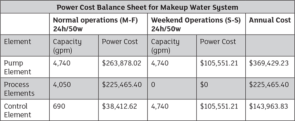 Image 2. The cost to run each element in the makeup water system for Monday through Friday and weekend operations.
Step 2: A Team Approach to Potential Solutions
With this amount of money on the table, the mill’s management assembled a working group to see what could be done. The insights of process, operations, controls, utility and electrical experts combined to find a resolution.
The operations department noted that the pipe’s length—21,000 feet—made turning the pumps on and off more complicated than flicking a switch. To stop them, an operator needed to slowly close the discharge valve to reduce the possibility of water hammer in the main header. Similarly, starting the system demanded that the operator throttle the discharge valve and slowly open it to prevent water hammer.
The electrical engineer mentioned that this gradual approach helped minimize the inrush electrical current at startup, but the same thing could be accomplished by installing a soft starter, an electronic device that limits the inrush current into the motor and minimizes the potential for water hammer in the main header.
The controls and instrumentation engineer suggested installing a variable frequency drive (VFD) on the pumps’ motors. VFDs allow the system to control the level in the reservoir instead of the current bypass control. They also include a soft-start capability. The electrical engineer further noted that the installation of the large discharge header (mentioned in last month’s article) reduced the motors’ electrical load. The pumps needed a 300-horsepower (hp) motor, instead of the installed 600-hp motor. That reduced the costs of the motors’ operation and the VFDs.
Operations pointed out that only two makeup water pumps were needed for system operation, so three pumps were all that was needed to meet operational requirements. They suggested removing two of the makeup water pumps.
The team identified an additional benefit. All the water passing through the existing bypass control had been processed by the treatment system before it returned to the river. Reducing the amount of unnecessarily treated water would reduce the consumption of chemicals and the wear and tear on the system’s mechanical equipment.
Replacing Bypass Control with a New Solution
After getting the information from the various departments, the plant engineer made five recommendations:
- Replace the existing bypass control with a level control loop on the surge tank.
- Install VFDs on the makeup water pumps as the primary element providing the required flow rate needed for operations and the final element in the level control loop.
- Remove two of the existing makeup water pumps from the pump house.
- Replace the existing 600-hp motors with 300-hp motors.
- Employ the soft start feature in the VFDs to eliminate the possibility of water hammer in the makeup water header.
Conclusion
By implementing all of these recommendations, the facility was able to realize an annual savings of $143,964 in operating costs. Much of the costs of the VFD and new motors was paid for by the salvage value of the two pumps removed from the pump house and the three oversized motors.
Thus, the intrepid plant engineer was able to turn 240 gpm in bypass control into major annual savings. More importantly, since everyone was involved in the decision-making process, multiple options were presented until a clear winner was chosen.
In my next column, we’ll shed light on the pump selection process, and see why most pumps are initially oversized.
To read more Pump System Improvement columns, click here.