


Magnetic force is a consequence of electromagnetic force, one of four fundamental forces of nature, and is caused by relative motion of electric charges. This phenomenon is at the heart of any electric motor, whether alternating current (AC), direct current (DC) or those with or without permanent magnets.
Most pumps are driven by AC induction motors. AC induction motors have a stationary outer member consisting of a core of laminated magnetic steel, with equally spaced slots distributed around the periphery. These slots hold the motor’s only electrical winding. This assembly is the stator.
The rotating portion of the motor is called the rotor and consists of a similar stack of slotted laminations. These slots form and hold the rotor conductors, referred to as the rotor winding, or cage. Generally, these conductors are diecast bars cast directly into the slots or made of extruded aluminum or copper material and driven axially into the slots. There is no electrical connection to the rotor winding.
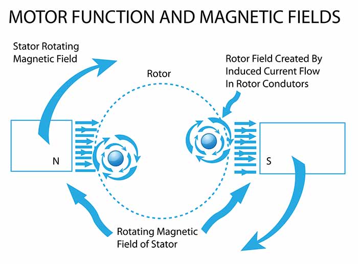 Image 1. Motor function and magnetic fields (Images courtesy of DSI/Dynamatic)
How does this function? When the AC stator winding is energized with AC current, the current establishes a magnetic field that varies in strength and polarization around the stator and rotates at a speed according to the winding design. When this field moves in close proximity to the rotor conductors (bars), a current is induced in the rotor winding. The current in the rotor establishes its own magnetic field, and the interaction produces torque.
To maintain this operation, there must be some relative motion between the stator magnetic field and the rotor bars. The rotor never quite reaches the speed of the rotating field, but operates at a slight slip, approximately 1 percent slower than the nominal speed of the motor.
The rotating speed of these motors is limited to a few selections, based on the applied AC frequency and the design of the winding. For 60 hertz (hz) applications, these speeds are 3,600 revolutions per minute (rpm) and any value divisible by an even number, i.e., 1,800, 1,200, 900, 720, etc.
Before the development of the variable frequency drive (VFD) in the 1960s and its commercial viability in the 1980s, users of pumps and other motor-driven mechanical equipment sought ways to derive variable speed from inherently fixed-speed AC motors. One development emerged as a popular choice and is alternately referred to as electromagnetic drive, magnetic drive, eddy current drive or eddy current clutch.
These terms refer to a machine that is driven by an AC motor at its inherent constant speed and use a DC excitation current to establish and control a magnetic field to achieve variable speed on a separate rotor.
The motor is directly coupled to a cylinder of magnetic steel, referred to as the drum or ring. It rotates at the motor’s constant speed.
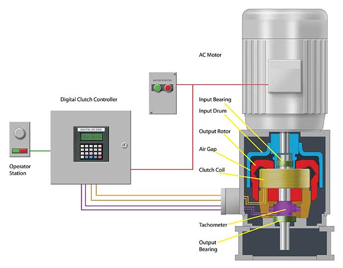 Image 2. Inside an eddy current drive
A separate rotor, called the magnet, is concentric with and inside the drum, rotating on a separate shaft. It consists of several coils of wire-wound poles made of magnetically active iron or steel. There are several designs for such a rotor, but all of them are connected to a small electronic controller that produces variable DC excitation.
When the excitation current is applied to the coil windings, the current establishes a magnetic field.
In a manner similar to, but “inside out” from the induction motor, this machine now has an unenergized conductive ring rotating in close proximity to a rotating magnetic field produced by the excited rotor poles on the magnet. This rotating field establishes a pattern of currents in the drum, called eddy currents. As in the case of the motor, these currents establish a magnetic field of their own, and the two magnetic fields interact to produce torque.
By controlling the DC current to the field coils, the strength of the magnetic field is controlled, and thus the torque. With torque available at any value on demand, speed of the driven equipment is easily controlled to a precise value, even as loads may vary. Like the induction motor, the underlying phenomenon of induced currents in the drum require a slip of about 1 to 5 percent, depending on the design and selection of the unit.
The magnetic, eddy current drive is suited for driving centrifugal pumps to control flow or pressure on a system with varying demand. In most applications, the pump varies only to a minimum of approximately 75 percent to achieve zero or minimum flow, and up to about 98 percent of motor speed. These limits vary slightly with every application.
The eddy current drive’s losses are dominated by the slip loss, which is essentially I2R loss in the drum, caused by the eddy currents and is proportional to the speed reduction and the driven load. A centrifugal pump’s load (brake horsepower) diminishes in proportion to the third power (cube) of speed reduction, thus any reduction of speed results in a net reduction in required power. Slip loss in the eddy current drive is easily dissipated to the ambient air as heat, with no requirement for air conditioning to maintain proper function.
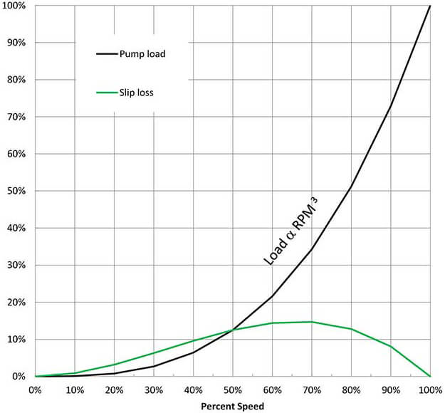 Image 3. Load reduction exceeds slip loss for every increment of speed reduction
The eddy current drive has earned a reputation for long-term reliable operation with only minimum and inexpensive maintenance. Many units use carbon brushes and slip rings to bring the DC excitation to the magnet rotor.
Periodic inspection and replacement of brushes and regular bearing lubrication is about all the maintenance needed for most applications. When properly applied and maintained, eddy current drives can last as long as the motors that drive them and the pumps they drive. Thirty to 40 years in service is common.