


How can I measure the power consumed by a pump in the field to compare to the OEM’s curve?
Monitoring a pump system’s performance through power measurements is a great way to evaluate the condition of equipment over time. Pump manufacturers typically publish the power required by the pump as a function of flow rate at a given rotational speed, which does not incorporate losses from other components. The input power to the pump is determined by measuring the torque and rotational speed at a given flow rate, or by measuring the electrical input power to a motor that has been characterized so that the motor input power can be correlated to motor output power (pump input power). Image 1 shows a typical performance curve.
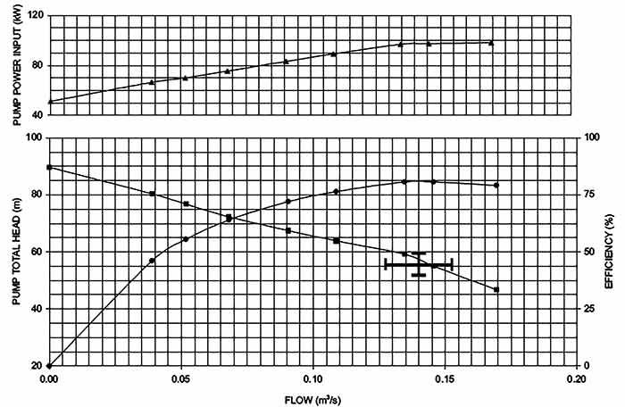 Image 1. Pump head, flow and input power vs. flow rate (Images courtesy of the Hydraulic Institute)
If a user is interested in trending the condition of the overall system (pump, motor, gear, etc.), then measuring the electrical input power to the motor or variable speed drive at a given flow rate and rotational speed is sufficient.
However, if the focus is monitoring the condition of just the pump and comparing it to the manufacturer’s pump curve, at a given flow rate and rotational speed, there are two options:
- Measure the pump shaft’s torque and rotational speed.
- Measure the motor electrical input power and incorporate the losses of the motor. If a variable speed drive or other equipment is used in the system, the losses of these components need to be considered.
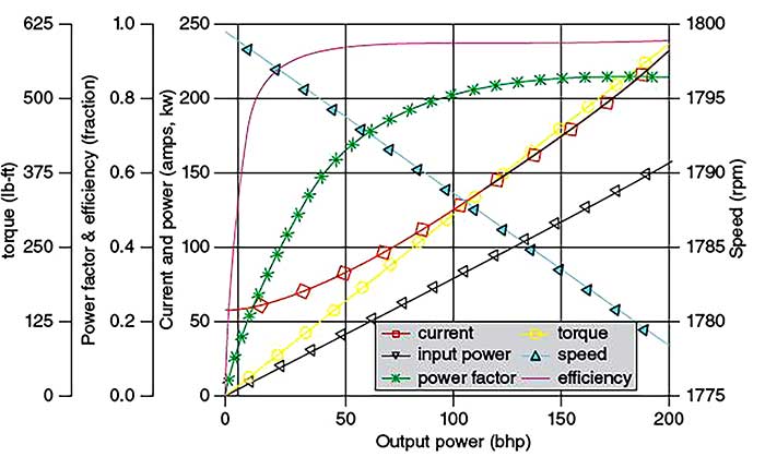 Image 2. Characterized motor performance curve
When assessing equipment in-situ, usually it is not practical to directly measure the torque on the pump shaft. Therefore, the second option is typically the most straightforward approach. The second option requires measuring the electrical input power to the motor and then correlating the motor input power to the output power. Image 2 is an example of a characterized motor curve (sometimes called a calibrated motor) used to correlate the motor input and output powers.
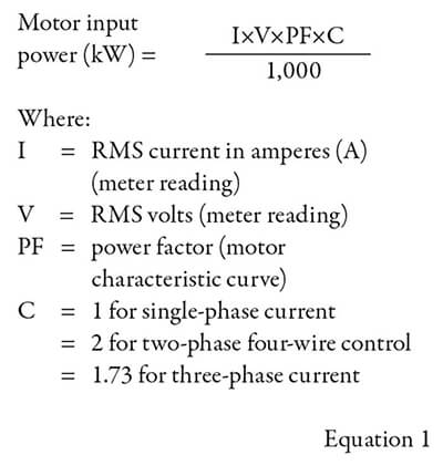
The power meter can be installed in the switch gear to measure the motor input power, or it can be calculated based on several individual measurements with the characteristic motor performance curve. As shown in the motor input power equation (Equation 1), motor current and voltage must be measured and power factor must be determined from the characteristic curve to calculate motor input power. Once the motor input power is known, the output power can be determined from the characterized motor performance curve.
Because the data displayed on manufacturers’ pump curves are typically based on 68 F water, users should consider:
- Is the process water-like?
- If the process fluid is not similar to the water test, the liquid density must be corrected. If the viscosity differs from the manufacturer’s test, the head, flow, efficiency and pump input power will be affected. ANSI/HI 9.6.7 Rotodynamic Pumps – Guidelines for Effects of Liquid Viscosity on Performance should be consulted.
- Is the in-situ test speed the same as the manufacturer curve?
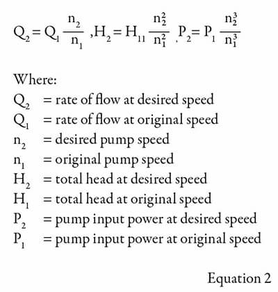
The manufacturer’s performance curve is typically represented at a constant speed. The pump performance will change with pump speed according to the affinity rules. The equations relating the rotodynamic pump performance parameters of flow rate, head and pump input power to speed are known as the affinity rules as outlined in Equation 2.
For more information on assessing pump systems, refer to the Hydraulic Institute’s Pump Systems Assessment Professional (PSAP) Certification Program at www.pumps.org/PSAP.