The Hydraulic Institute’s new test standard, ANSI/HI 14.6 Rotodynamic Pumps for Hydraulic Performance Acceptance Tests, provides the pump community with a globally accepted standard for testing rotodynamic pumps of the centrifugal, mixed flow and axial types. It supersedes two test standards: ANSI/HI 1.6 Centrifugal Pump Tests and ANSI/HI 2.6 Vertical Pump Tests. The new standard features significant changes in test acceptance requirements and in educational content. It also includes “must-know” requirements for anyone involved with the hydrostatic or performance testing of pumps.
With ANSI/HI 14.6, two significant standards now have identical pump acceptance test criteria with worldwide acceptance. The other is ANSI/HI 11.6 Rotodynamic Submersible Pumps for Hydraulic Performance, Hydrostatic Pressure, Mechanical, and Electrical Acceptance Tests.
For more than a decade, the previous versions, ANSI/HI 1.6 and ANSI/HI 2.6, served as the standards that defined testing requirements for centrifugal pumps. ANSI/HI 14.6 has similar test methods and procedures but with noticeably different changes to test acceptance requirements and informational details. The updated standard is also formatted and organized in a way that provides quick and easy access to information regarding rotodynamic pumps; terms and definitions; multiple acceptance tests; various testing procedures; and an array of useful information regarding pump characteristics, performance and guidelines.
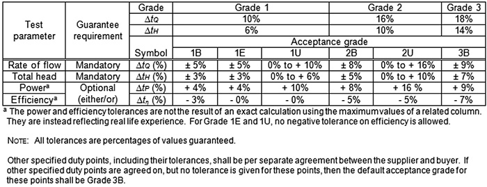 Table 14.6.3.4. Pump test acceptance grades and corresponding tolerance band
ANSI/HI 14.6 is meant to be used for acceptance testing at pump test facilities or laboratories only and cannot be used in its entirety for testing in the field. This standard applies to the pump (flange-to-flange relationship), without any fittings. However, additional information regarding pump testing with fittings and other equipment can be found in the standard’s appendices. If contractually agreed upon by the manufacturer/supplier and the purchaser, the pump may also be tested with a combination of fittings.
The differences between the previous versions of the test standard and the new standard are significant enough to warrant the pump community’s attention.
New Terms
These terms appear throughout the body of the standard as well as in the appendices:
- Normative: “What is written in the standard must be adhered to comply with the standard.” (ANSI/HI 14.6, p. vii)
- Informative: “Written to inform and educate the user and do not require compliance.” (ANSI/HI 14.6, p. vii)
- Guarantee point: “The specified and contractually agreed on rated point (duty point).” (ANSI/HI 14.6, p. 10)
- NPSH3: “Unless otherwise specified, a 3 percent drop in head (the accepted industry practice) will be used to determine NPSHR and defined as NPSH3.” (ANSI/HI 14.6, p. 19)
These terms clarify to the pump community to which processes and procedures they must adhere and which may be recommended for further consideration. NPSH3 allows the pump community to know exactly what percentage of a drop in head is used to determine the NPSHR (required), removing ambiguity regarding that value. As a result, NPSH3 is used instead of NPSHR.
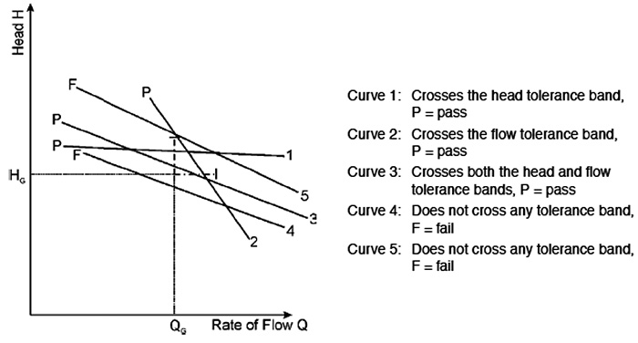 Figure 14.6.3.4.2a. Unilateral tolerance acceptance
General Sections
Throughout ANSI/HI 14.6, the pump community will find sections labeled “General” for pump acceptance tests, measurement uncertainty, test procedures and test arrangements, hydrostatic pressure testing, recommended tests, NPSH test requirements, measurement of pump power input, and special test methods.
These sections provide an introduction and background information in advance of the substance and specific procedures of the topics. This added feature helps the document flow from section to section and highlights the importance of the respective topics.
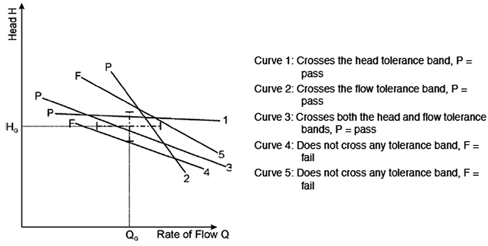 Figure 14.6.3.4.2b. Bilateral tolerance acceptance
Acceptance Grades and Tolerances
Pump performance acceptance grades for flow, head, efficiency and power are used in ANSI/HI 14.6 when evaluating the acceptance of a pump for a guarantee point. Note that power or efficiency can be specified but not both. The previous versions used two grades of accuracy for pump acceptance criteria, while ANSI/HI 14.6 uses three. Table 14.6.3.4 is an addition to the new standard and is used to refer to acceptance grades and tolerance bands.
Six pump performance test acceptance grades are used: 1B, 1E, 1U, 2B, 2U and 3B. Grade 1 is the most stringent, and the “U” specifies having a unilateral tolerance band. The “B” specifies having a bilateral tolerance band. Acceptance grade 1E can be used when energy efficiency is of importance and is also bilateral.
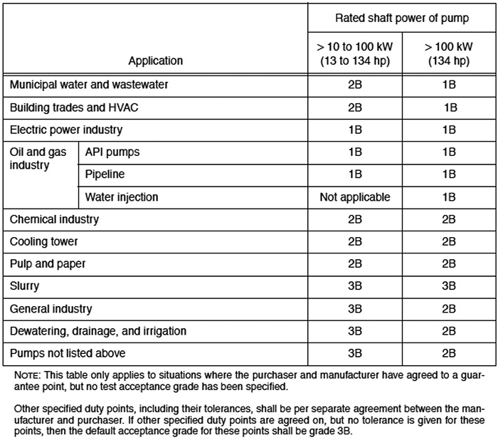 Table 14.6.4. Default acceptance grade based on the purchaser’s intended service
The purchaser and manufacturer must agree on a specific grade to use and judge if a particular pump will meet a guarantee point. If no acceptance grade is specified, the standard reverts to the default test acceptance grade in Table 14.6.4.
Guarantee Point Evaluation
An evaluation of flow, head, power and efficiency will be conducted. Guarantee point evaluation shall be performed at the rated speed. To determine whether a pump meets the acceptance criteria, a plot of pump total head versus flow is produced and measured against the corresponding tolerance bands for the specified acceptance grade. The guarantee point for acceptance is defined as flow and head for one set of conditions. In a similar fashion, the efficiency and power plot versus rate of flow are produced and measured against the tolerance bands for the specified acceptance grade.
This new standard explains how to use tolerance bands to determine if the pump meets the acceptance criteria. Agreements should be reached between the buyer and seller as to the amount of uncertainty allowed for acceptance.
Depending on the acceptance grade, the tolerance bands can be unilateral or bilateral, with those tolerance lines forming a cross. As long as the pump head capacity curve passes through at least one of the arms of the cross, pump performance is acceptable.
For a unilateral tolerance band, only two hash marks label the limits of the length of two arms for the capacity curve to pass through, not allowing for negative tolerances. With a bilateral tolerance band, four arms are available for the capacity curve to pass through, allowing for positive and negative tolerances.
The hash marks on the horizontal head line represent the limits of flow tolerance, while the hash marks on the vertical flow line represent the limits of head tolerance. For the curve to successfully meet the acceptance criteria, it must pass through the line and not the hash mark. See Figure 14.6.3.4.2a for some unilateral and bilateral acceptances.
Small Pumps
This new standard addresses the acceptance criteria for “small” pumps with a shaft power input of up to 10 kilowatts (kW) (13.4 horsepower—HP) but larger than 1 kW (1.3 HP). Characteristics of these pumps include a low horsepower, small impeller diameter and smaller size dimensions. As a result of these characteristics, a wider efficiency tolerance is permitted than what is specified in Table 14.6.3.4 because those tolerances may be too stringent.
Due to the characteristics of these small pumps, they are much more sensitive to normal manufacturing variations and mechanical losses can vary, comprising a large portion of the power used to drive the pump. In addition, during testing, additional measured quantities are often small and more difficult to measure. These factors influenced the new adoption of the following tolerance bands for pumps with an input power of 10 kilowatts (13.4 horsepower) and less:
rate of flow tQ = ± 10%
pump total head tH = ± 8%
The manufacturer and purchaser should agree on a set of tolerance factors to use when testing smaller pumps. If the pump has an input power of 1 kW (1.3 HP) or less, special agreements regarding tolerance factors between the manufacturer and purchaser should be made.
Test Recommendations
A section describing recommended tests, other than acceptance tests based on pump flow and head delivered, has been included in the new standard. This section is located in Appendix D and includes information on test types based on pump type. The types of tests include performance, hydrostatic, NPSH and mechanical. Table D.1 (from Appendix D) is a guide when determining additional testing for the pump.
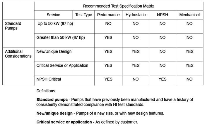 Table D.1. Matrix of recommended tests
String Test
Another important addition is Appendix G (string test), which covers performance testing of the entire pumping system—including the motor, pump and drive (for example, gearbox, belt drive, etc.). This is a less accurate method of determining the true pump efficiency, since the input power to the pump shaft is calculated by accounting for the published motor and drive efficiencies. Since these efficiencies are not known precisely, this method of calculating pump input power is less accurate than when the shaft torque and rpm are directly measured.
When a variable frequency drive (VFD) is used as part of the string, obtaining an accurate value of input power to the pump shaft becomes difficult. Although many VFDs provide an output power measurement, the value of this power is approximate and usually not accurate enough for acceptance testing. This reading also does not account for the reduction in motor efficiency when operated on VFD power. Table G.1 can be used to compare influencing factors for calculating pump efficiency for string test configurations.
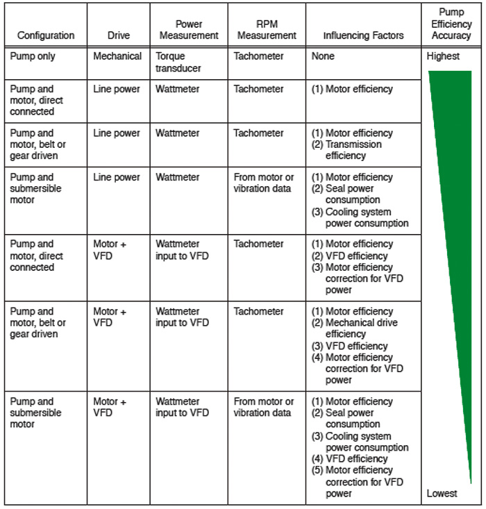 Table G.1. Influencing factors for calculating pump efficiency for different configurations
Hydrostatic Pressure Test
The hydrostatic test pressure and test duration have been updated. The test pressure relates to the rated pressure at the ambient temperature of the item to be tested and is determined by the following equation:
ptest = K1 x K2 x prated
Where:
ptest = the hydrostatic test pressure
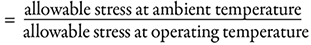
prated = the rated pressure at operating temperature
K1 = a factor whose value shall be determined by the pump specification, but shall not be less than 1.3, except for thermoset parts
K2 = a factor whose value shall be determined by the material strength, as follows