


Seal failures are the number one headache for many operators when it comes to pump reliability concerns. However, these failures are usually indicators of an underlying issue. Seal failure is rarely caused by a problem with the seal’s design or a fault during seal or bearing production.
The primary reasons seals fail are:
- improper operating flow (significantly off the best efficiency point [BEP])
- absence of (or poor) seal flush for dirty liquids
- poor alignment (driver to pump, or piping to pump)
When pumps operate off BEP, the hydraulic radial load can be hundreds of times greater than the weight of the impeller. Therefore it is the radial load—not the overhung weight—that causes the damage. Any seal manufacturer will tell you that deflection over as little as 0.002 inches and the resulting loss of faces parallelism will kill the seal, or at least cause excessive leakage.
L3/D4 is a measure of pump rotor stiffness, or its ability to resist radial load and to minimize deflection. It comes from the basic cantilevered beam deflection formula:
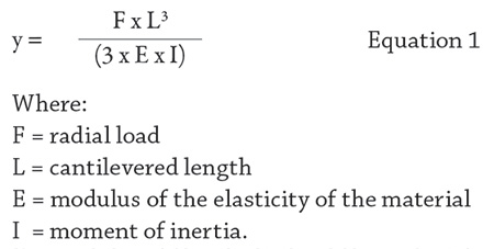
For a circular shaft I = 3.14 x D4/64, and thus a deflection at a given force is proportional to:
y ~ L3/D4, or abbreviated it is often written as L3D4
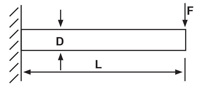 Figure 1. The pump shaft deflects under load, as a structural beam. (Graphics courtesy of the author)
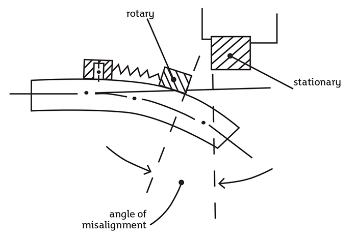 Figure 2. Seals will leak as excessive loads cause shaft deflection and seal face misalignment.
Thus, L3D4 becomes a criterionfor an indirect assessment, or a comparison, of a rotor deflection under load.
American National Standards Institute (ANSI) pumps have L3D4 ratios in a range from 20 to 120, with the smaller number preferred.
You can easily determine the L3D4 ratio of your pump by measuring the length of the shaft from the center of the bearing closest to the impeller and impeller centerline, and the diameter of the shaft under the bearing. Then cube the length, raise the diameter to the fourth power, and this is the ratio. A shaft diameter changes from the bearing towards the impeller, but its value under the bearing is taken nominally. You can make your own plant database of L3D4 for different pump designs.
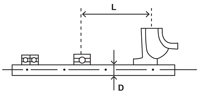 Figure 3. L and D parameters for a pump rotor.
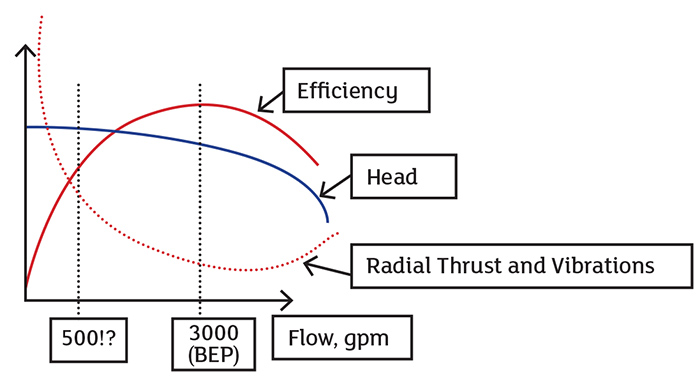 Figure 4. It is the high hydraulic radial thrust—and not the weight of the impeller—that causes excessive deflection and seal failures.
As a quiz: Can you quantify (by the actual example) the magnitude of a seal deflection for a typical end suction pump by considering weight of the impeller versus hydraulic radial load at 50 percent BEP operation? The best answer wins free attendance to Pump School.
Question for Dr. Pump
Mike Wisnoski
Reliability Engineer, John Crane
Upon reading a recent article I had a few questions regarding the “Pressure (Head) Method.” Isn’t this method only valid for pumps with suction/discharge sizes that are equal? eg 3x3 or 4x4, etc. Thus, is one better served to find flow for a said pump in the field by using the following method:
- Measure differential pressure at the pump. Convert to head etc.
- Pull pump curve and look at performance line for pump with impeller installed.
- Determine the velocity head for several points on performance curve line.
- Subtract total head shown on pump curve from velocity head from a.
- Replot head vs. flow using this new head. (Basically static head + elevation)
- Use this curve as compared with field measurements as this is what is measured in the field using gauges. (Unless pitot tube is used)
Dr. Nelik’s reply:
Thanks for your question, Mike. Essentially, you are correct—I did not account for the velocity head differences between discharge and suction. In some instances this can matter a lot, but in most cases, the field testing objectives are not to obtain performance within tight accuracy but to get a relatively approximated results.
In the field, the typical environment is much “rougher” than in the factory. The objective is not absolute precision, but a method that is simple with the fewest corrections possible.
I find people report a problem when a 10,000 gallons per minute (gpm) pump pumps little, say 8,000 gpm or less. Rarely do people find themselves in a position to know if it is 10,000 gpm, or 9,800 gpm.
It is a different world out there versus the laboratory environment, which I experienced as a pump design engineer for pump manufacturers.
At any rate, thank you for your observation, and a perceptive comment.
Best regards,
Lev Nelik