


Rotating liquid pump shafts that are originally sealed with soft packings mostly use contacting face seals, also known as mechanical seals. Typical rotational speeds are roughly between 1,000 and 3,600 revolutions per minute (rpm). In turbomachinery—such as compressors and expanders—the rotational speeds are higher and mechanical seals would not immediately appear to be an option, due to greater rubbing speeds along with a lack of liquid cooling and lubrication. Nevertheless, from the late 1970s when they were first marketed, noncontacting mechanical seals, known as dry gas seals in cartridge form, have been used in most gas turbomachinery.
The first, and still the bulk, of these dry gas seal applications are through-shaft or beam machines where the shaft, carrying multiple closed impellers, is supported at each end, also known as “between-bearings” compressors.
Shaft speeds range from near 20,000 rpm down to under 3,000 rpm for the biggest machines. The latter have shaft sizes up to 350 millimeters (mm), approximately 13 3/4 inches diameter.
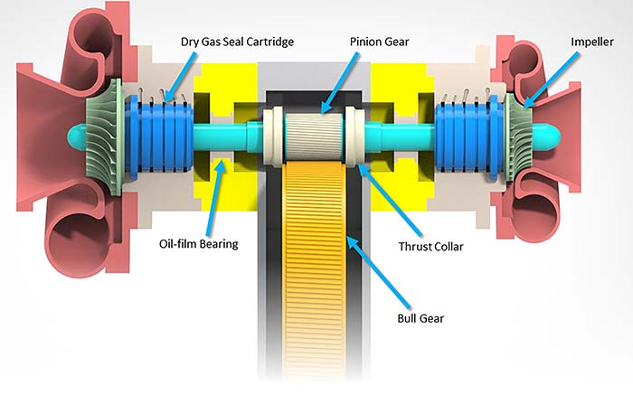 Image 1. Section of an overhung, integrally geared compressor (Images courtesy of John Crane)
Smaller, between-bearing machines run at higher speeds. The fastest machines are single-ended or overhung shaft types with open impellers in individual casings, typically referred to as integrally geared compressors (see Image 1). Such machines vary from single-stage to multiple-stage designs with several compressor casings driven by more than one shaft, usually off a central bull gear wheel. They are used in refineries and chemical plants for a range of processes from simple fuel gas requirements to complex multipressure applications. There is presently a growth area in the compression of carbon dioxide (CO2), which is a difficult-to-seal critical fluid.
For many reasons, as far as the shaft seal is concerned, the established between-bearing compressor applications may be seen as straightforward compared to those for overhung machines. The typical layout of a dry gas seal stage is as shown in Image 2.
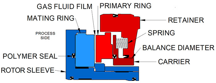 Image 2. Typical dry gas seal stage
Once the seal is pressurized, a thin fluid film of the sealed gas separates the stationary primary ring and rotating mating ring. The gap between the faces is typically 2 to 4 micrometer (µm) thick, but depends on the pressure, speed of the application and nature of the gas. This thin film must continue to separate the faces during significant axial movements of the shaft. Fortunately, the fluid dynamics involved are advantageous. As the gap tries to close, the fluid film becomes stiffer and increasingly resistant to the faces coming into contact.
There are two important implications associated with using a gas film seal in this way. First, there is some leakage to be considered, but this is small (measured in single or tens of standard-liters/minute) because of the small gap.
Second, because contamination is the most common cause of seal failure, the inboard area must be supplied with conditioned process gas, or an alternative, to ensure the seal is operating on clean dry gas. For the same reason, it is necessary to avoid contaminating the seal with liquid lubricant from the bearing adjacent to the seal. A separation seal is usually provided. These range from a simple labyrinth to a number of contacting or noncontacting devices, usually of a double gas-buffered design.
Dry gas seals are supplied in cartridge form, most commonly in a tandem arrangement with the inboard stage followed by an outboard stage. A double, back-to-back, inert gas buffered arrangement is sometimes used. It is possible to have a single-stage seal. This is most commonly the case in high-speed, overhung machines where space for the seals is limited.
With a single or unbuffered seal, careful thought must be given to the nature and destination of the leakage. A separation device may help.
Although there is a wide range of parameters, a typical between-the-bearings compressor may have a shaft size of 120 mm (4 3/4 inches) diameter and a rotational working speed of around 12,000 rpm. This gives a passing speed at the seal faces of about 100 meters per second (m/s) on a shaft supported at both ends and driven through a coupling with a degree of flexibility.
The rotor dynamics in turbomachinery are usually monitored by measuring the radial vibrations outboard of the shaft support bearings. Gas seals can withstand most normal levels of vibration in a turbo compressor, including brief transients into surge at levels acceptable to the compressor.
The noncontacting face seal is intrinsically tolerant of radial vibration, as the faces separated by a film of gas can easily slide eccentrically against each other. The seal does not provide much damping force to, and absorbs little energy from, such movements.
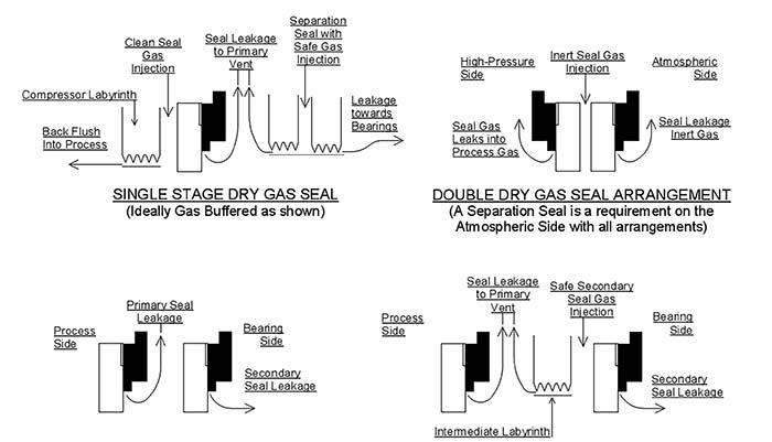 Image 3. Typical dry gas seal arrangements
The stability of the seal under the axial component of any vibration is maintained by the stiffness of the fluid film and the responsiveness incorporated into the seal design. The shaft seal assembly must take up any relative axial movement between the rotor and the casing of the compressor.
Between-the-bearing machines usually have a thrust bearing at one end of the shaft. This means that, at the thrust-bearing end of the machine, the amount of sudden axial movement is limited in the seal (typically around 0.1 mm to 0.2 mm in operation).
The overhung compressor presents opportunities to create more arduous modes of vibration than a beam machine. The higher speed machines are now rotating at between 30,000 rpm to 60,000 rpm with a small diameter shaft supported only on one side of the seal and driven directly from a large bull gear. The bearing is adjacent to the bull gear and the mass of the compressor impeller carried at the unsupported end of the shaft. A wide range of resonances may be generated. There are additional excitations from various passing frequencies of the impeller vanes and the gear drive in close proximity to the seal.
In integrally geared compressors, the axial thrust in the directly driven shaft is often taken on thrust collars bearing against the bull gear. This can lead to axial modes of vibration that may be detrimental to the gas seal. Swashing in the thrust collars will lead to small synchronous axial vibrations, but significant oscillations are more likely to come from the bull gear at subsynchronous frequencies.
Dry gas seals operated within integrally geared compressors can often have design enhancements specifically to combat some of the idiosyncrasies of the application. The seal face passing speeds on high-speed machines can
be in excess of 160 m/s. This, with the small diameters, leads to large centrifugal loadings.
The selection of secondary sealing elements, such as O-rings and polytetrafluoroethylene (PTFE)-based seals, is constrained by the pressure and temperature ranges of the application and chemical compatibility requirements. In high-speed applications, also consider how the sealing element reacts to centrifugal forces.
Flexible polymer U-ring seals are energized by a combination of the sealed pressure and an integral spring. In applications where test regimes require a combination of low-pressure and high-speed running, the sealing element’s spring force may be insufficient to ensure adequate contact loads between sealing surfaces. Therefore, bespoke polymer seal designs can be used to address such issues.
Finite element analysis techniques predict the effects of high-rotational forces, pressure and temperature effects, which can allow the designer to accommodate such requirements. Focus is often on sealing elements such as those between the shaft and main sleeve or behind the mating ring.
Adverse effects on the seals can be attributed to torsional vibrations within the shaft. These may be generated by unevenness in the gear drive, but also from the variable speed inverter controls in electric drives, or variable frequency drives (VFDs), which may not produce a completely smooth signal.
The rotating sleeve assembly should have drive features, such as keys and lugs, to ensure all parts rotate as one. A component, like the stationary primary ring, should have antirotation features interlocking with metal components. Areas of intercomponent engagement can be damaged by vibrational hammering and fretting.
Another focus of design is the balance diameter polymer seal. Although not subject to rotational forces, it should be free to slide and accommodate the axial movements of the rotor, whatever the seal’s state of pressurization. As a direct result of the means in which the thrusts on the pinion shafts of integrally geared compressors are managed, the seal should be able to cope with constant axial deviations. In some instances, the total accumulated distance travelled by the balance diameter seal can be thousands of kilometers over a typical five-year installation life.
The material combination, contact loads and environment of operation are key considerations when designing these sealing elements. A combination of tribological performance and robust design can ensure integrity over the life of the seal.
Next Month: Offset and reducer expansion joints considerations
We invite your suggestions for article topics as well as questions on sealing issues so we can better respond to the needs of the industry. Please direct your suggestions and questions to sealingsensequestions@fluidsealing.com.