


The expression “less is more” usually does not ring true in our field. Yet, as we search for more throughput, capacity and efficiency, adding more pumps or new and more powerful pumps is not always the answer.
It can lead to the wrong kind of “more”—more money laid out for capital expenditures, more utility costs, and more disruption and downtime.
“More” is needed, but what might really be required is a more careful examination of an entire system to find a solution that meets the business needs of the organization: to optimize productivity, recover revenue, be more profitable and—yes—deliver the right level of system performance.
This was the challenge that a nickel mine and processing mill in Western Canada recently faced. It first thought that it needed to add more horsepower (hp) and newer and larger pumps to meet increased demand for makeup water. By modeling the proposed new system, it discovered that new pumps could drive up electrical costs by as much as 50 percent. The mine also found that the installation process could shut down the mill’s operations for up to two weeks.
By looking at the entire system, instead of simply focusing on the pumps, the plant staff was able to meet the system’s process requirements without replacing the existing vertical turbine pumps. Shelving the initial plan, the plant engineer determined that by increasing the diameter of the makeup water pump head and adding a second, wider pipe in parallel to the existing water header, they could meet their objectives for makeup water capacity. This would result in a lower cost in electricity without a demand charge increase, and without a substantial penalty in downtime for installation and switchover.
Let’s take a closer look at how the mill and its engineers arrived at a solution.
The System as Found
The mine and mill had been in operation for three decades. Over the years, the makeup water system capacity increased to keep up with expansion. Impeller stages to the vertical turbine pumps were added to meet the increased flow and pressure demands. Five years ago, the mill added two pumps to meet the increased flow rates (Image 1).
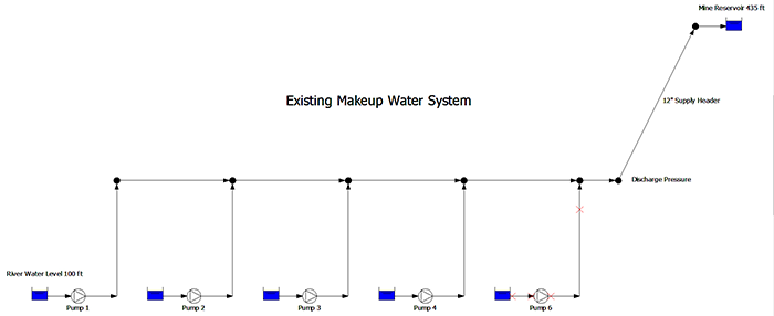
Image 1. Example of an existing makeup water system (Image courtesy of the author)
Then, during its most recent expansion, the mill reevaluated its choices. After looking at the makeup water pumps, the desired system flow rate of 4,500 gallons per minute (gpm) could not be achieved using the existing pumps.
The mill considered replacing the existing vertical pumps with five new pumps that were better suited to meet the increase flow rate.
Spike in Electrical Consumption
At the outset of the proposed mill expansion, the plant engineer measured a flow of 4,170 gpm using an ultrasonic flow meter. It was determined that the pumps had reached the maximum number of stages. The team considered running five pumps in parallel to achieve the needed flow rate. During a test with all pumps running, the measured flow rate was 4,600 gpm. Since the plant’s operating procedures require a standby pump for all service systems, the plant needed to add a sixth pump to the system, but there was no space in the pump house for the standby.
The team modeled the makeup water system with a piping simulation program. Because the results of a simulation are only as accurate as the data entered, the manufacturer’s pump performance curve data was entered into the simulation software for accuracy.
When the calculated results matched the observed discharge pressure with four pumps in operation, a simulation with five operating pumps was compared to the results of the five-pump test. Once again, the calculated results closely matched the observed plant data. With an accurate representation of the physical piping system in hand, the pump head requirement was calculated.
A subsequent simulation for the new pumps revealed the possible major increase in the electrical load. The electrical engineer discovered the larger pumps required a 50 percent increase in electrical power consumption.
The utility engineer calculated the increase in pumping power and determined it would result in a substantial increase in the mill’s demand charges from the electrical utility.
What’s more, the plant engineer projected that the makeup water system would need to be out of service for two weeks to replace the pumps, requiring the installation of temporary pumps to keep the plant in operation. Based on these expenses and productivity disruptions, the mill’s managers investigated other options. The simulation showed that the 12-inch discharge header had a fluid velocity of 16 feet per second. The test, therefore, uncovered another problem: a pressure drop of more than 500 pounds per square inch (psi) in the main header.
It was suggested that the best way to reduce the system electrical load was to increase the pipe diameter of the main header, thereby reducing the system’s pump head requirements. Using this information, new options were available.
Problem Solved
Ultimately, the mine inserted a 20-inch pipeline parallel to the original 12-inch diameter main header. With the two pipelines in parallel, the average fluid velocity in the main headers was 3.5 feet per second, resulting in a pipeline head loss of 52 feet.
The existing 12-inch header with a flow rate of 4,500 gpm resulted in a pump head requirement of 1,500 feet. Installing a 20-inch header parallel to the existing header resulted in a pump head requirement of 388 feet of fluid.
The reduction in head loss allowed the plant to reconfigure the original vertical turbines’ pumps to five stages. Additionally, only two of the reconfigured pumps were needed to achieve a system flow rate of 4,740 gpm.
The reduction in head loss also resulted in savings of 1,618 kilowatt (kW) per hour with a savings of $969,144 in pumping costs. Since the facility’s total electrical power consumption went down, there was no increase in the electrical utility’s demand charge. And, the new 20-inch diameter parallel makeup water pump was installed while the existing system remained in operation with only a single day needed to make the tie-in.
Thus, a more system-wide view enabled the mine to:
- achieve its desired makeup water flow rate without replacing existing vertical turbine pumps
- reduce downtime from two weeks to one day
- avoid unnecessary electrical costs and demand charge increases
There was one loose end. The new makeup water system flow requirement was 4,500 gpm, but the actual flow rate was 4,740 gpm when operating with two reconfigured pumps. This resulted in an excess flow rate of 240 gpm. So, what happens to that extra 240 gpm? After the 4,740 gpm is pumped to a reservoir, the 240 gpm of excess flow returns to the river. This is referred to as bypass control, common in many piping systems.
In the next column, we’ll explore how much the bypass control costs and if there are ways to save.
To read more Pump System Improvement columns, click here.