


The pumps referred to in this article are two supply pumps with a flow of 36,500 gallons per minute (gpm), head at 2,200 feet and 27,000 horsepower (hp) that move seawater 200 kilometers (km) to be injected into an oil reservoir to maintain a high pressure. The suction line distributes flow to two first-stage impellers, which discharge to two second-stage impellers (Image 1).
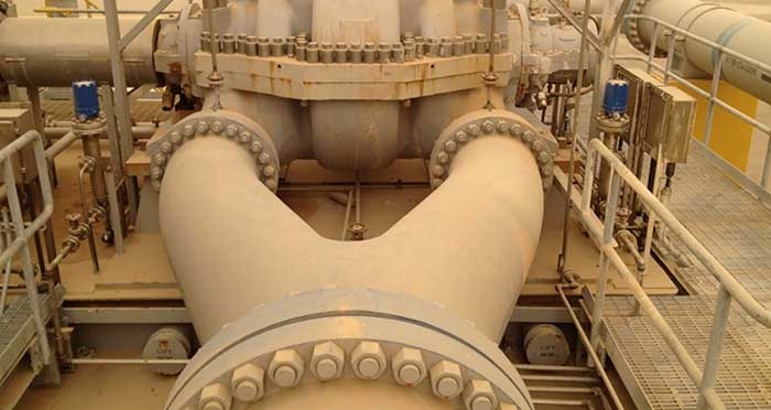 Image 1. Supply pumps field installation (Images courtesy of Saudi Aramco)
After more than 22,500 hours of operation, the first pump tripped on high vibration and was removed from service. A dismantle inspection revealed a fractured non-drive end (NDE) second- stage impeller (Image 2).
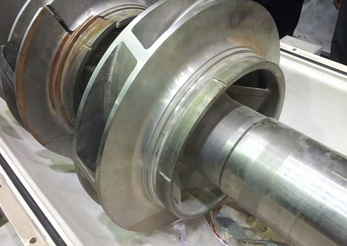 Image 2. NDE first- and second-stage impellers.
Among the findings: impeller wear rings missing from the two stages on the NDE half of the pump; wear caused by impeller rings rubbing on the casing and channel ring; and a broken antirotation pin at the center bushing. With the exception of minor nicks caused by broken wear rings and impeller vanes passing through the pump, the remainder of the pump appeared in good condition. Damage to the Babbitt surface of the radial bearings was considered the result of the impeller fracture and did not contribute to the failure.
With the spare rotor installed and running successfully, the second pump was removed from service and inspected. During this inspection, vane edge cracking was found at the leading edge of the second-stage impeller on the NDE half of the rotor (Image 3).
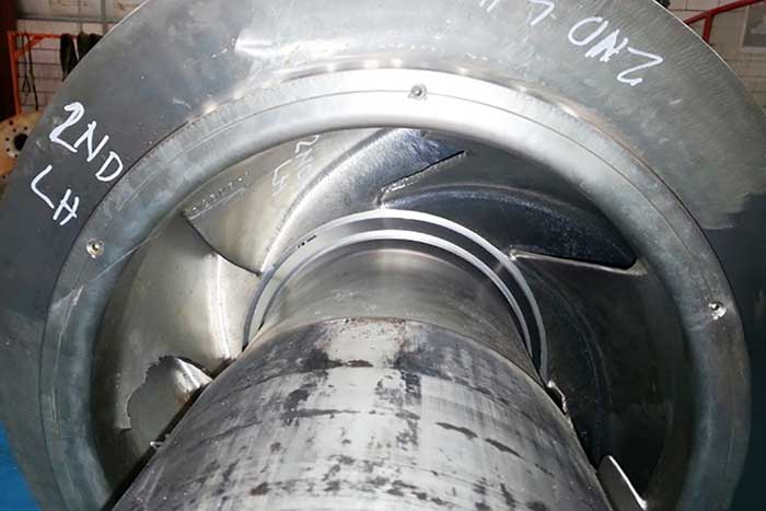 Image 3. Second pump NDE second-stage impeller.
A crack was also found by dye penetrant inspection on the second-stage impeller on the drive end (DE) half of the rotor. There was no indication of cracking or damage to the first-stage impellers, or any impeller at the outer diameter (OD) sections of the shroud.
The two pumps exhibited some consistency in the cracking location and appearance. The second-stage impellers experienced the cracking, while the first-stage impeller was undamaged.
It appeared that the wear ring was dislodged due to inadequate interference fit. This is supported by the fact that the second pump also failed without losing any of the wear rings.
The failed impeller of the first pump was subjected to a thorough metallographic analysis. Also, the failed impeller from the second pump was sent to the material laboratory for metallographic analysis.
Findings & Discussion
The laboratory report confirms that the second-stage impeller materials were in accordance with chemical and physical properties specified for the impeller. It indicated casting defects in a piece of vane as a “cold shut,” and suggested that defect may be a contributor to the failure (Image 4).
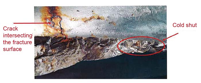 Image 4. Cracked surface of the impeller inlet vane.
Stresses were verified on the second- stage impeller by applying a pressure load to the inner surface of the impeller bore, simulating the interference fit between the shaft and impeller. The load was computed to represent a 0.005-inch interference fit (on the diameter). The design interference fit ranges from 0.003 to 0.005 inch on the diameter.
Mechanical analysis, using the software solver and finite element analysis, revealed peak stresses at the leading edges of the vanes, which neared the maximum allowable stress for the material. The combination of hydraulic load, inertia and interference force produced the maximum stress observed in the impeller at the leading edge of the impeller (Image 5).
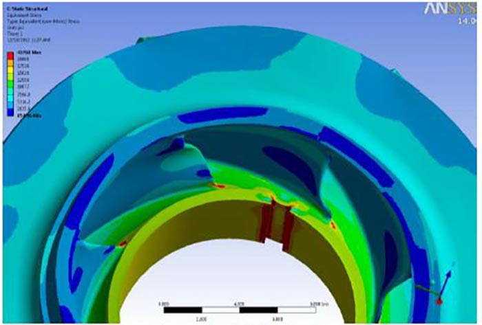 Image 5. Second-stage impeller with 0.005 inch interference fit
Since the stress levels predicted that the leading edge of the vane was conforming to crack locations at the inner portion of the impeller, this analysis suggests a potential cause for the failure of the second-stage impeller (Image 6).
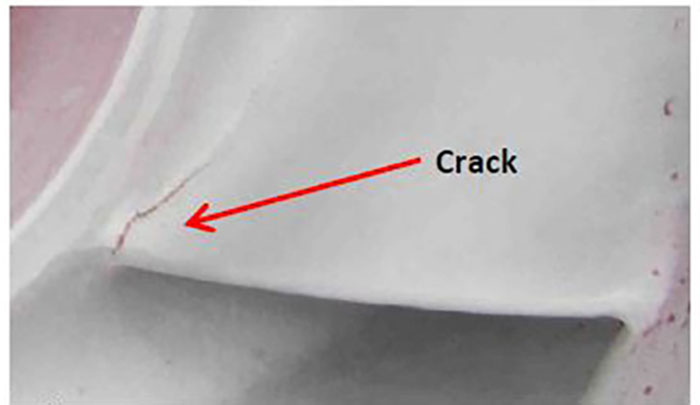 Image 6. Second-stage, leading edge crack (GT6001) dye penetrant inspection
The root cause of the failure was determined to be highly localized stresses at the second-stage impeller inlet vane leading edge, exceeding the material of ASTM 351 grade CF3M. This was due to cyclic hydraulic loads and excessive interference fit. Also, casting defect “cold shut” was a contributor to the failure.
Recommendations
To extend the life of the second-stage impellers and eliminate the source of the inlet vane cracking, the following were implemented:
- The impeller material was upgraded from austenitic stainless steel (ASTM A351 gr. CF3M) to super duplex stainless steel (ASTM A890 gr. 5A).
- The range of the interference fit between the impeller and shaft was reduced from the range of 0.003 to 0.005 inches to 0.001 to 0.003 inches.
- The wear rings were eliminated, and the wear surface on the impeller was overlaid with tungsten carbide, using the direct laser deposition process.