


Is there a simple way to check the alignment of flexible couplings on a pump?
Laser alignment systems are used to determine the extent of shaft misalignment by measuring the movement of a laser beam across the surface of a detector plate as the shafts are rotated. Many laser alignment systems are available, and the procedure for alignment is provided by the laser system’s producer. They are capable of aligning couplings with and without spacers and are most commonly used for precision alignments. Image 1 shows an example of a laser alignment system setup on a pump and motor shaft. By following the instructions of the laser system, the computer will output adjustment requirements to align
the shafts.
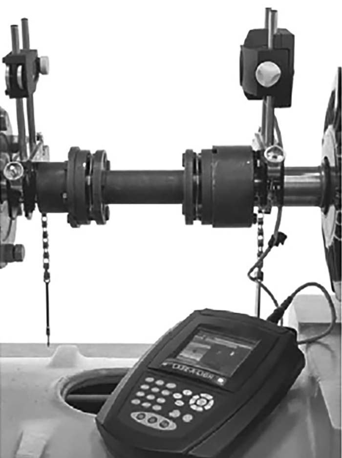 Image 1. Laser alignment system (Images courtesy of Hydraulic Institute)
In the absence of a laser alignment system, users can check the alignment with some simple tools. The necessary tools used for checking the alignment of a flexible coupling are a straightedge and a taper gauge or a set of feeler gauges, or by use of dial indicators.
A rough check for angular alignment is made by inserting the taper gauge or feelers between the coupling faces at 90 degree intervals (see Image 2). Checks for angular and parallel alignment by this method can only be done if the face and outside diameters of the coupling halves are square and concentric with the coupling bores. A rough check for parallel alignment is made by placing a straightedge across both coupling rims at the top, bottom and at both sides (see Image 3). After rough alignment, fasten the indicator to the pump half of the coupling, with the indicator button resting on the other half coupling periphery (see Image 4). Set the dial to zero, and mark the coupling half beside where the button rests. Rotate both shafts by the same amount, i.e., all readings on the dial must be made with the button beside the mark. The dial readings will indicate whether the driver has to be raised, lowered or moved to either side.
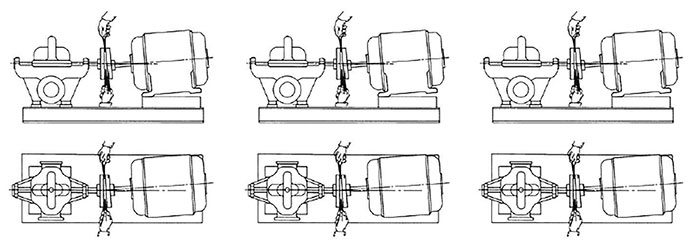 Image 2 (left). Angular misalignment. Image 3 (center). Parallel misalignment. Image 4 (right). Dial indicator
After each adjustment, recheck both parallel and angular alignments. Accurate alignment of shaft centers can be obtained with the dial indicator method—even where faces or outside diameters of the coupling halves are not square or concentric with the bores—provided all measurements for angular alignment are made between the same two points on the outside diameters. For angular alignment, change the indicator so it bears against the face of the same coupling half and proceed as described for parallel alignment.
There are additional techniques not described in this answer that are required for proper pump alignment, such as correcting for indicator sag or compensating for cold aligning a hot pump system. Please reference industry standards and the pump and coupling manufacturer’s instructions as well.
For more information about coupling alignment for rotodynamic pumps, including additional considerations, see the American National Standard ANSI/HI 14.4 Rotodynamic Pumps for Manuals Describing Installation, Operation, and Maintenance at pumps.org.