


There are several diverse ways to design expansion joints. As the design evolves, each variation requires testing and validation to ensure the expansion joint is performing in the targeted range. Validation testing could take a long time and cost a lot of money if every variation is sent to a third-party testing facility. That is why it is crucial to have in-house testing capabilities when manufacturing performance expansion joints. Eliminating factors such as lead times and shipping allows designers to receive test results quickly.
This grants more time for design, development and making necessary alterations to the expansion joint based on said results. The financial savings of in-house testing capabilities allow for more resources to be invested into the design. These savings will also benefit potential buyers, as the cost of the expansion joint remains unaffected by third-party testing prices. The most beneficial aspect of in-house testing is the freedom to customize testing. Without testing constraints, expansion joints can undergo testing in unique real life application states opposed to standardized methodology.
1. Burst Test
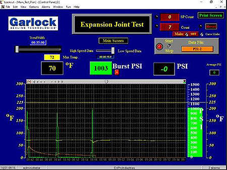
During burst testing, an expansion joint is pressurized until failure occurs. Failure takes place either in the material or at the sealing flange. This test simulates the effects of pressure surges in a pressurized piping system. The results from the burst testing will determine the expansion joint’s safety factor rating. The industry standard safety rating is 3:1, but for a performance expansion joint, the performance rating should exceed all standardized values. Developing a performance expansion joint with the highest pressure rating in the industry and backed by an atypical 4:1 safety factor results in the safest, most reliable expansion joint in the market. To claim a statement as such, the expansion joint should endure several functional tests simulating actual field conditions.
The ability to perform this testing in-house during the design and development phase generates accurate results in a timely manner. Using engineering resources in creating in-house testing capabilities allows users to test outside the normal standard size range. Additionally, this provides the performance expansion joint with another advantage to the standard expansion joint. Generally, larger-sized expansion joints have burst ratings generated by stress calculations. Designing in-house burst testing capabilities allows the joint to be designed and rated to its highest potential. This will allow the performance expansion joint to be marketed with confidence and backed by validation testing throughout the entire size offering. Utilizing electromechanical components such as pressure transducers and a data acquisition box will provide test data throughout the entire process and display the exact pressure value upon burst failure.
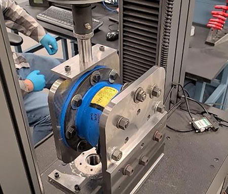
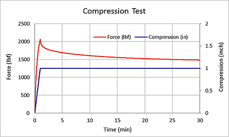
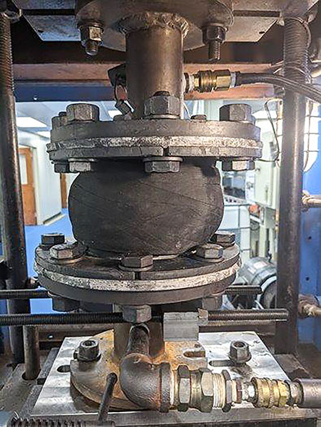
2. Spring Rate Test
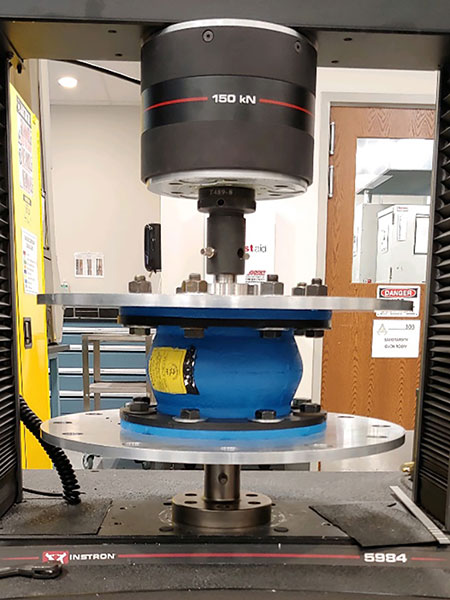
In “Expansion Joints – Piping Technical Handbook,” the Fluid Sealing Association (FSA) defines the spring rate as the force required to move the expansion joint a certain distance in compression, extension or laterally. It is most often expressed in pounds (lb)/inches (in). In the real world, a tensile tester with properly designed tooling and fixture is used to measure the spring rate of an expansion joint (Image 4[a] and [b]). In the case of a compression spring rate test, an expansion joint is compressed at a specified deformation rate from its neutral position to achieve a given compression deformation (inch). The force (lb) to deform the joint would be measured and recorded throughout the test. The spring rate in compression direction can then be calculated through the following equation. The same test principle also applies to spring rate tests in elongation and lateral direction.
3. Vacuum Test
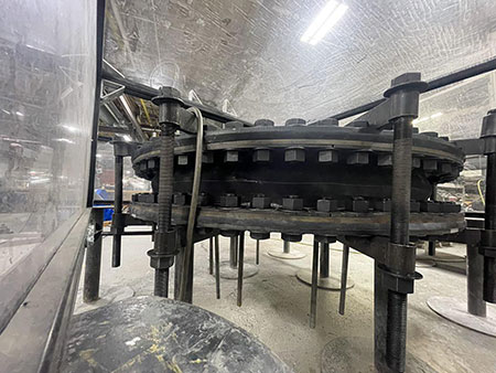
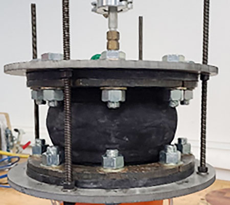
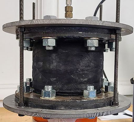
During a standard vacuum test (FSA-PSJ-701-19), negative pressure is pulled up to 26 inches of mercury for 10 minutes to ensure the layers of the joint do not delaminate and pull apart. The standard method of testing for vacuum only ensures a joint will withstand this negative pressure in a neutral state. In application, a joint is unlikely to only see a neutral state—elongation and compression are typical deformation states of an expansion joint. These deformed states apply different stresses on the layers of material within the joint. To this effect, a modified vacuum test was developed to simulate this worst case application. This test was developed following FSA-PSJ-701-19 standards with the addition of a gradual elongation of the joint and requiring 29 inches of mercury. A full 10-minute vacuum cycle is performed at four equal elongation intervals, with the first interval being a neutral state (Image 5) and the final a fully elongated state (Image 6). This elongation puts the joint under maximum rated conditions during vacuum testing to ensure optimal performance.
movement testing
4. Movement Test
To best simulate end user applications, a nondestructive, modified hydrotest was recently developed. This new testing involves simulating the movement and pressures a joint could experience in the field. Performance expansion joints have an established maximum service pressure along with a maximum elongation or compression movement.
These variables are tested in tandem by displacing the joint to the maximum ratings, pressurizing and holding for 10 minutes. The acceptance criteria for this test are an absence of visible deformation and no leakage from the joint. Many expansion joints also have a specification for lateral movement, prompting the need to test this additional variable. To mimic this variable, the joint is installed in a modified movement test stand, deflected to the maximum rated lateral movement and pressurized to maximum rated pressure for 10 minutes.
Major consideration has gone into the development of vacuum, spring rate, movement and burst testing to best simulate end user applications of expansion joints. Achieving all these criteria in-house provides users with reliable results and the highest quality expansion joint possible at a reasonable price.