


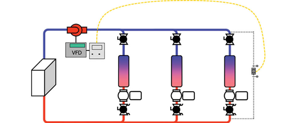
A pump used to circulate water for heating or cooling typically serves multiple areas that need heating or cooling (zones). These zones are controlled by individual thermostats, which open or close a zone valve, allowing the water to circulate to that area for heating or cooling. If a single pump is used to serve multiple zones (Image 1), the flow and pressure will change as zones open and close. A pressure sensor can be used to monitor the pressure and adjust the speed of the pump so it operates at a lower speed when fewer zones are open.
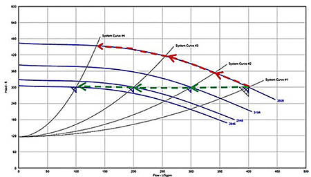
In Image 2, the green arrows show constant pressure being maintained (pressure control) as fewer zones are calling for water. Note that the pressure is maintained at 300 feet as the flow rate is reduced from 400 gallons per minute (gpm) to 100 gpm. The red dashed lines illustrate the flow rate and pressure that would occur without reducing the speed to maintain a constant pressure. The pressure increases from 300 feet of head to about 450 feet, and the flow reduces from 400 gpm to about 140 gpm. Since most systems operate at part load, the reduction in flow rate and pressure using the variable speed pressure control can result in significant energy savings. For the example in Image 2, if the pump operated 5,000 hours per year and the electricity cost was $0.15/kilowatt-hour (kWh) while operated primarily at part load (which is typical), the energy savings would be about 33,750 kWh annually. This equates to about $5,000 annual energy cost savings. In addition, the reduced speed operation will result in the pump operating closer to its best efficiency point, which will improve the overall reliability of the pump.
For more on controlling pumps in commercial buildings, refer to the Hydraulic Institute’s Pump System Optimization for Commercial Buildings at training.pumps.org.