


Over years of use in the motor industry, the term “inverter duty” for motor ratings has become watered down. Whenever someone refers to an inverter duty motor, they are usually referring to a higher insulation class for the windings.
The term inverter duty means much more than just windings. There is an entire standard written to give recommendations on what an inverter duty motor should include. This standard, American National Standards Institute (ANSI)/National Electrical Manufacturers Association (NEMA) MG1 Part 31, dives into excess shaft currents from pulse width modulation (PWM) waveforms, motors starting with capacitors, bearing recommendations and even environmental concerns.
The Basics: Labeling & Environment
To identify whether a motor is inverter duty rated from the nameplate, users will want to look for a couple pieces of information. First, “Inverter Duty” labels are an easy giveaway. Occasionally, there will be a label that says “VT/CT,” meaning variable torque/constant torque, which is also an indicator that a motor meets NEMA MG1 Part 31.
The recommendations in the NEMA standard assume that motors on variable frequency drives (VFDs) will be operated
in what they consider a normal environment. To be considered standard, a motor must be:
- 7,200 volts (V) or below
- installed at 1,000 meters (m)
- (3,300 feet) or lower
- within a -15 C to +40 C ambient temperature range (or stricter, depending on the lubrication style
- of the bearings)
- rigidly mounted
- free of ventilation interference
If the motor conditions do not fall in the standard category, users should talk to the motor manufacturer about the capabilities of the motor. It is surprisingly often that motor installations are not considered normal. Common variables that may make the situation unusual could be:
- environmental contaminants such as dirt, humidity or radiation
- operation in a classified environment, meaning the presence of combustible or explosive dust, gas or materials
- unusual forces on the motor, including heavy vibrations, strong sideways
- force on the shaft or particularly fast or tough use
- applications requiring multiple motors for each piece of driven equipment
Windings & Insulation
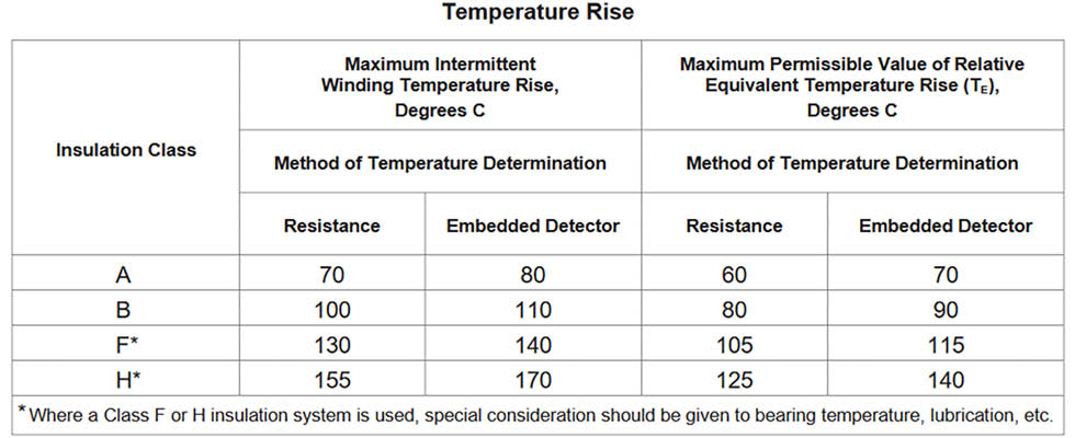
The insulation in the motor must be capable of withstanding the voltage spikes that a VFD may send, especially when
the lead length from VFD to motor is over 100 feet. The tables in NEMA MG1 Part 31 give the exact information on the insulation requirements needed.
In practice, 1,600 V insulation is considered the minimum. Most consider class F insulation with class B
temperature rise to be the minimum for most situations where high voltage spikes from a VFD are possible.
Bearings & Grounding
VFDs also create excess shaft currents that damage bearings, causing fluting and pitting. The NEMA standard recommends motors where the shaft voltage is over 300 millivolts peak to have insulated bearings on the non-drive end (NDE). VFD-caused harmonics can also cause issues if the motor is not properly grounded.
The standard mentions multiple ways to address issues of excess voltage on the shaft, including:
- adding filters
- improving system grounding
- adding shaft grounding technologies
An approach addressing the issues on multiple fronts is usually best. It is recommended to add shaft grounding rings (SGRs) on all motors running on a VFD. Larger or more critical motors should have insulated bearings combined with SGRs for longer life.
When the lead length from VFD to motor is over 100 feet, it is recommended to add output filtering on the VFD itself. This will often be a load reactor or dV/dt filter at lower lengths and a full sine wave filter at higher lengths. This practice is also recommended at cable lengths under 100 feet when the motor is especially critical or difficult to replace, such as
down-well motors.
Other Considerations
The service factor of a motor is its ability to occasionally run while overloaded. Many motors come with a 1.15 or 1.25 service factor, meaning 15% or 25% overload capability. When running on a VFD, however, all motors should be considered a 1.0 service factor according to the NEMA standard.
The standard also warns about power factor or surge suppression capacitors in between the VFD and the motor. The most common problem users encounter is when retrofitting a VFD into a system where there was not one before, as there may be surge suppression capacitors on the motor that need to be removed.
What Is the Industry Doing?
While the NEMA standard gives many recommendations, most motor manufacturers are implementing higher standards. Where 1,600 V insulation may be the minimum, inverter duty motors often have 2,000 V or 2,200 V insulation as the standard. Some manufacturers are even moving to class H insulation in certain motor lines. Many use a double dip and bake method for varnish that will make the motor stronger.
On the VFD side, many manufacturers are tailoring the exact output filtering to the application. Many technological advancements have made reactors much better at filtering, often comparable to a dV/dt filter. Sine wave filters are becoming more common as electrical rooms are consolidated in clean areas of facilities and longer lead lengths become common.
What Should Users Be Doing?
VFDs are a great way to increase process control, save energy and even perform some mechanical tasks such as deragging in a water system. As they are added, users may see instances of motor damage increase. There are a few steps one should take to increase the life span of motors on VFDs.
First, verify that motors are truly inverter duty per the NEMA MG1 Part 31 standard, meeting insulation, bearing, grounding and other requirements. Second, verify that additional protections such as insulated bearings, SGRs and VFD output filters are being utilized.
Third, speak directly to motor suppliers or manufacturers about the system and concerns. Many water systems only deal with motors occasionally, while these motor suppliers deal with them daily. They will be able to quickly help identify issues that may have been missed.