


Why are bearings and seals considered in pump rotor dynamics? The reliability and mechanical performance of a modern pump depends heavily on the rotor dynamic design of the machine. At its core, the goal of rotor dynamics is to prevent excessive vibrations and instabilities, which are greatly affected by the dynamic characteristics of a machine’s bearings and seals. This makes these components a key factor in performing accurate analysis and reliability predictions since they provide stiffness and damping to the system.
Although rotor dynamics analyses are similar for any rotating machine, pump rotor dynamics have specific challenges that must be addressed. Since pumps typically handle high-density liquids, the dynamic effects of liquid seals become even more important. Stiffness and added mass coefficients generated by liquid seals dramatically change the pump’s critical speed. These coefficients depend on several factors, such as clearances between the shaft and stator, the liquid properties, and more. Because of this, there are distinctions between dry and wet conditions and between new and worn conditions for clearances. When the seals possess certain characteristics due to being in wet conditions, they redistribute and change the bearings’ loads during operation.
The bearing and seal simulation should be interconnected with related analyses, including secondary flow path modeling. This is useful for obtaining boundary conditions, determining the hydrodynamic parameters for seals and bearings and calculating dynamic coefficients (stiffness and damping).
Simulating Bearings
A variety of bearings can be used to support a pump rotor train, and their effects on rotor dynamics can vary greatly. The most common bearing types used for pump applications are rolling element bearings and hydrodynamic oil film (sliding) bearings. Sliding contact bearings are employed when the service conditions (speed, radial and axial loads) no longer allow the use of rolling contact bearings; for example, when the equipment is running above 3,000 rotations per minute (rpm) and its power exceeds 500 horsepower (hp). A typical bearing can be modeled with four stiffness and four damping coefficients, which are direct and cross-coupled.
To determine these coefficients, bearing modeling should be based on accurate physical effects simulation.
For these bearings, detailed simulations are usually based on a finite-difference or a finite-element solution of Reynolds equations, which are expanded with heat conduction equations. This method provides accurate results even for complicated designs. Although engineers may default to a powerful simulation method such as computational fluid dynamics (CFD) analysis, this approach is not always used in practice due to the complexity of modeling and the extended calculation time. Instead, it can be simpler and better to model the bearing and simulate its performance characteristics in 1D, which uses less power and resources to gather simulation results faster.
Approaches for rolling element bearing simulation vary substantially depending on the task. The advanced methodologies for rolling element bearings that give an exact solution for Hertzian contacts are the elastic, elastohydrodynamic lubrication (EHL) contact models, and the finite element method. However, such advanced methods require significant computational resources and model preparation, so obtaining a solution using this approach is also quite time-consuming. In practice, to determine stiffness coefficients and estimate bearing heat generation, simpler semi-empirical approaches can be used. Usually, friction power is taken into account for the bearings’ configurations, loads and their resistance coefficients. The resistance coefficient includes dimensionless correlations such as Reynolds and Euler numbers. The friction power is calculated as a function of the resistance coefficient, bearing geometry data and fluid density at the bearing’s temperature. The required oil mass flow rate, which is necessary for cooling down the bearings, can be found from the thermal balance equation.
As mentioned earlier in this article, bearings and seals should not be simulated inside of a bubble. Instead, it is important to take into account related systems such as the overall oil lubrication system. This system is not just responsible for lubricating the moving parts and surfaces, it also cools them. The lubrication system usually contains supply and discharge channels, as well as nozzles. A goal when designing these systems is to get an estimate of the pressure levels that will generate an adequate lubricant mass flow rate while also ensuring acceptable oil velocity. To prevent charring, oil friction, and other negative effects, an increase in the oil level will not do the job. Thus, the discharge channels must ensure proper oil removal. The most effective solution to these problems is to use a 1D thermal-fluid network approach.1 This approach enables the engineer to quickly build a network that is based on preliminary data, which is necessary to verify initial parameters for further hydrodynamic and mechanical bearing characteristic simulations.
Simulating Seals
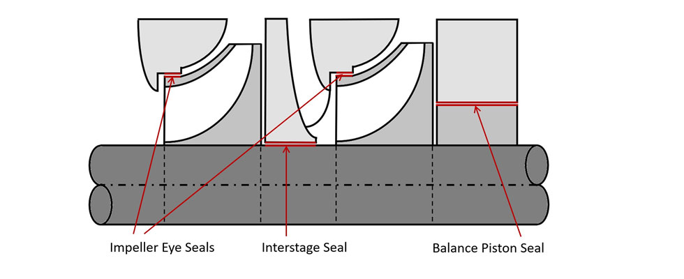
Depending on the purpose, pressure values and the working fluid, different types of seals are used in pumping equipment. These include liquid annular, labyrinth, impeller eyes and lip seals. The typical design of a pump includes various seals (annular/labyrinth), which are presented in Image 2. Depending on the location, these seals can be interstage, impeller eyes and balance piston types.
A liquid seal’s effect on the rotor dynamic performance of the machine is similar to a bearing (i.e., seals introduce stiffness, damping and added mass). Thus, rotor dynamic models should incorporate additional spring-damper-mass elements. The total force generated in each seal is dependent on the abovementioned factors as well as rotor deflections, velocities and accelerations in their locations.
A common and effective approach to simulate seal behavior in a rotor train is the Childs2 method, named for Dara Childs, former Turbomachinery Lab director at Texas A&M University. Childs developed the formulas for stiffness calculations and damping coefficients for liquid and gas annular seals. The formulas contain a number of initial parameters including rotor rotational speed, inlet swirl ratio, fluid viscosity, liquid annular seal radius, axial and circumferential Reynolds numbers, and more. These are integrated into several commercial codes due to the multifaceted nature of this approach.
Accurate inlet and outlet parameter calculations for seals are the key challenge for dynamic coefficient analysis. Predicting pressure levels in secondary flow paths is not a trivial task and requires a model of the entire hydraulic system. The flow behavior in sealing components is complex. Moreover, it is influenced by a rotational wall that swirls the flow in the seals and a stator wall that slows it down. If the rotational installation works with a high-temperature working fluid, the inner wall from the fluid side heats the flow in the sealing components. Pressure drops, leakages and working fluid heating can be estimated through 3D CFD. However, as previously mentioned, this is time-consuming and requires sufficient engineering efforts, not to mention computational power. Thus, in engineering practice, the 1D thermal-fluid network approach can be regularly used to resolve these problems, which uses correlation equations to calculate the resistance or discharge coefficients.
Bringing it All Together
Since pump reliability depends on different design considerations, taking an integrated approach is a key strategy for development. This allows engineers to ensure that no design considerations are neglected and that machine reliability is ensured. Secondary flow analysis as well as proper analysis of the lubrication system needs to be considered alongside rotor dynamics. Additionally, bearings and seals, which have their own stiffness and damping properties, need to be considered as part of the rotor train for a pump to perform properly and efficiently. In short, multifaceted problems must be resolved with multifaceted tools and approaches, which is why there is a trend toward process integration and automation in the design/analysis space. The illustrations below show an example of this within an integrated platform.
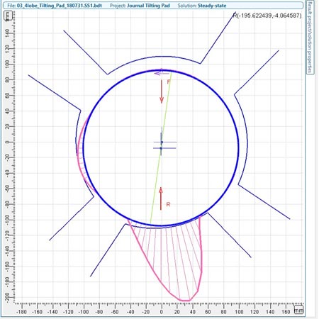
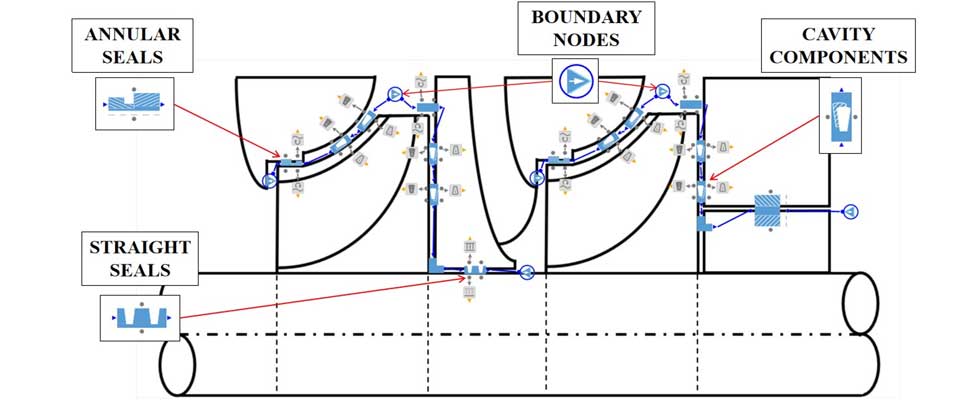
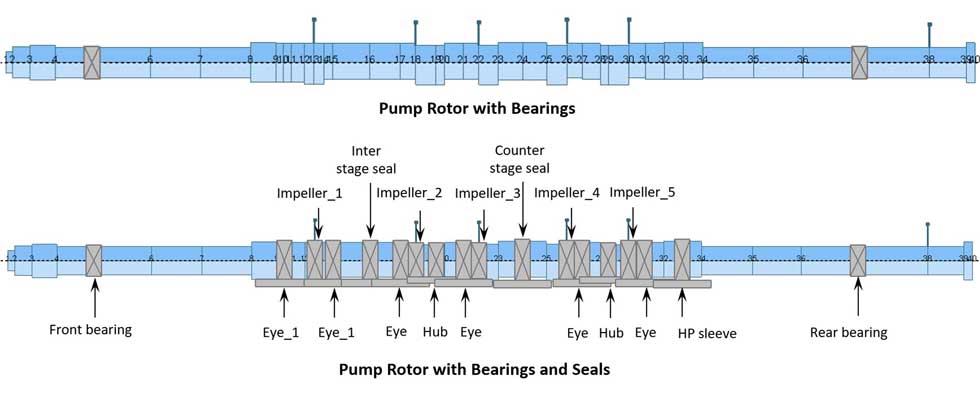
Image 4 presents an example of a 5-stage rotor dynamics pump model. This model includes the rotor, bearings and seals. The bearing characteristics have been calculated and imported into the model (Image 1). The corresponding pressure level estimates and leakage flow rates in the secondary flow path were modeled and can be seen in Image 3.
This process was and should be simulated as a coupled task. By taking an integrated and multifaceted approach, and using validated methods like 1D thermal networking modeling, engineers will be able to determine if the pump’s rotor train has been properly supported, as well as lubricated, which will ensure a long service life for the pump.
References
1. Khandrymailov A., Moroz L., Yevlakhov V., Staple S., and Vogel G. “An Approach to Model a Lossless Junction for Fluid Network Calculations in Turbomachinery.” Proceedings of ASME Turbo Expo 2020. GT2020-16079. Sept. 23, 2020.
2. Childs D.W. Turbomachinery Rotordynamics: Phenomena, Modeling, and Analysis. New York: Wiley, 1993.
3. Idelchik, I. E. Handbook of Hydraulic Resistance. Begell House, New York (2008).