


Harsh environments challenge the personnel charged with asset reliability and uptime. Heat, dust, dirt, moisture, steam, salt, sticky fluids and caustic chemicals are some of the exacting factors that exist in harsh applications—which include those in the oil, gas and ethanol industries.
These challenges are compounded when sealing valves, rotating equipment and the lubricants that keep rotating assets up and optimally operating.
With rotating equipment, two types of seals are vital for reliable operation: process seals and oil seals.
Process seals seal the pumped fluid and prevent it from leaking out of the pump’s stuffing box or seal chamber to the environment or toward the drive end of the system. Many different process seals are available for rotating equipment:
- packing
- mechanical seals
- lip and other elastomeric seals
- magnetic-face seals
Oil seals seal the lubrication for the bearing housing and drive. Without an oil seal, any process fluid that may escape the stuffing box or outside contaminants from the atmosphere will contaminate the lubrication. This contamination will increase the need for lubricant replacement and will likely accelerate bearing failure.
The seals available for lubrication sealing are:
- lip and other elastomeric seals
- magnetic-face seals
- bearing isolators
Selecting the ideal seal for the process and lubrication is important to improve uptime and reliability. Three examples illustrate how different seal technologies can make an impact in different industries and applications.
API 622 Packing for Valves
Regulations for fugitive emissions from valves continue to tighten. Identifying the ideal packing to comply with American Petroleum Institute (API) 622 may be a challenge. Ideally, the packing needs
to be:
- nonhardening
- nonshrink
- withstand high temperatures and pressures
- compatible with nonoxidizing chemicals, hydrocarbons and steam
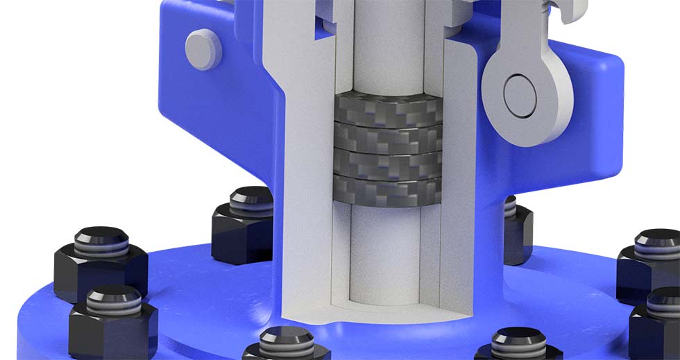
In the oil and gas industry, many ingredients (dust, grit, high temperatures and pressures, and remote locations with limited access) combine to decrease asset life and damage packing. Damaged packing leads to leakage and a lack of regulatory compliance. Selecting a valve packing (see Image 1) with the following characteristics may help minimize these issues and maintain API 622 compliance:
- braided and preferably graphite
- temperatures up to 1250 F (676 C) in steam or nonoxidizing atmosphere and 850 F (454 C) in oxidizing atmospheres
- pressure up to 500 pounds per square inch (psi)
- pH range of 0 to 14
Mechanical Seal System for the Ethanol Industry
Ensuring that the equipment used in ethanol production remains in operation is paramount. In particular, sealing evaporator and syrup pumps present difficult challenges in this industry.
The thick, abrasive nature of the elevated-temperature mixture that travels from evaporator pump to evaporator pump causes many issues. It also gets thicker as it moves through the pumps, ultimately forming a syrup. This viscous, hot mixture causes many mechanical seals to fail prematurely. These harsh conditions may cause catastrophic damage to mechanical seals and contaminate the lubricant and bearings as well.
A systems approach to sealing these pumps includes the selection of a rugged mechanical seal, using the proper barrier fluid and barrier fluid tank, and ensuring that the correct pressure is applied and maintained. This all helps improve reliability and increase uptime.
Ethanol Case Study
One ethanol plant engineer in the Midwest experienced repeat mechanical seal failures. The challenging application caused several problems. The plant engineer struggled with:
- detecting seal failure
- setting up the barrier fluid tank
- correct location relative to the pump
- installation of the piping and tubing
- correct thermo-siphoning
- proper barrier fluid selection
- premature failure
- improper installation
- pump misalignment
- mismanagement of the seal chamber environment
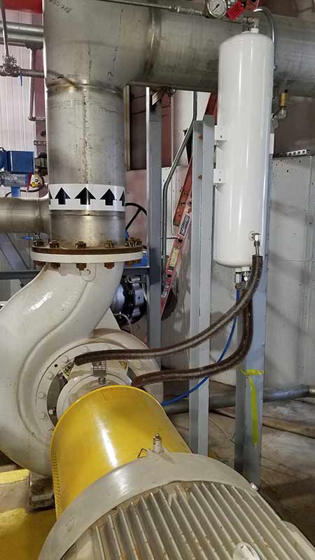
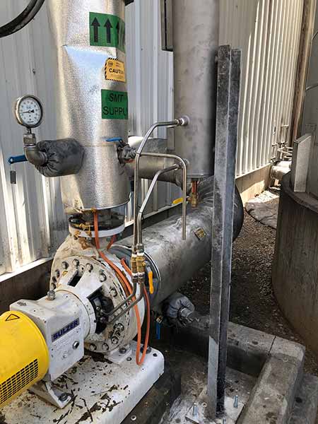
To solve the problem, the engineer first needed to know why the seals continually failed (see Image 2). The mechanical seals were analyzed by a seal manufacturer. This analysis identified the multiple, system-wide reasons that the seals failed prematurely. A new mechanical seal system solved the failures. The new seal system (see Image 3) benefits were:
- A mechanical seal with an integral pumping ring helped move more heat from the seal to the reservoir for cooling.
- The tangential flush connections allowed for 360-degree heat removal from the seal chamber. A more robust barrier fluid was also used. This combination solved the tank and barrier fluid issues that plagued the team.
- Proper training of the maintenance team by the seal system manufacturer improved installation, operation and maintenance. Some aspects of mechanical seals were not necessarily intuitive to the team members doing the installation.
- The mean time between repair (MTBR) increased from 12 to 15 months to 37 months.
12 to15 months to 37 months.
Bearing Isolators for All Equipment
Traditional contacting, compound labyrinth bearing isolators with dynamic O-rings have become a common way to protect bearing lubrication. This technology has been important in the advancement of rotating equipment reliability. However, the technology also has limitations.
Some of the limitations of traditional isolators include:
- wear caused by a contacting lip seal
- the inability to block contaminants during static conditions, such as during shutdown
Taking a system approach, a bearing isolator designed for real-world conditions must provide a higher level of protection for a longer period of time compared to other available technologies.
The oil seal must be a true noncontact (throughout its life), vertical labyrinth seal. It must eliminate all contamination, including the more aggressive contaminants that may enter the housing during shutdown, as shown in Image 4.
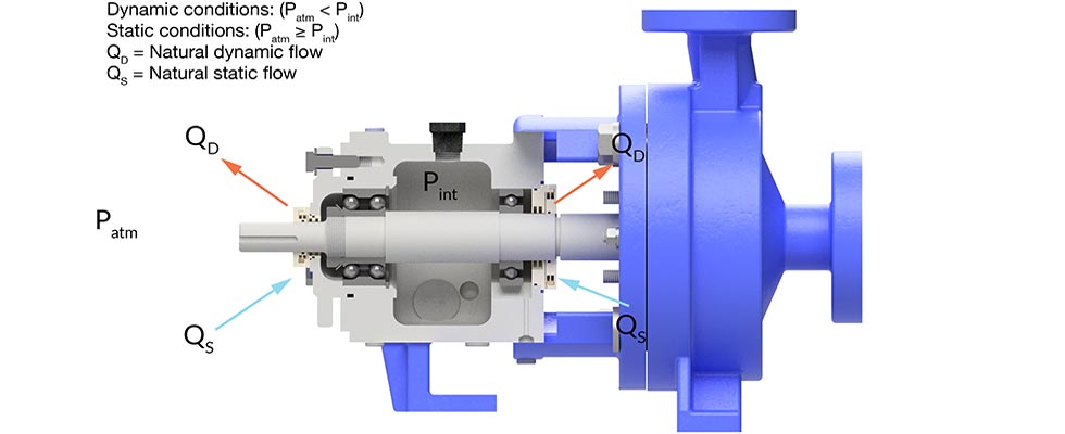
Image 4 shows how the housing vents to the atmosphere under dynamic conditions. By plugging the breather/vent and directing the air through the noncontact seal, the seal can control the bearing housing environment. Once the escaping air enters the seal body under dynamic conditions, the close internal clearances between the stator and rotor create disk friction, adding energy to the escaping air.
This creates a high-pressure circumferential area at the exit of the seal that assists in keeping contaminants out. Combined with the expelling action of the rotor, long axial and radial throttling gaps, and no expulsion port, contamination ingress into the seal is difficult.
Static sealing presents more of a challenge for a true noncontact seal. Under static conditions, the bearing housing begins to draw air in from the atmosphere as it moves to equilibrium with the environment. As the airborne contaminants and vapor are drawn through the seal, the energy is broken down because it is forced through the axial throttling gap. It then continues through the longer radial gap where the contaminants’ energy is broken down further. Moisture and other contaminants are captured within the internal condensate trap and allowed to drain out of a small static weep hole at the 6 o’clock position of the bearing isolator. The static O-rings create throttling gaps that break down the remainder of the contaminants’ energy and direct it to the condensate trap to be drained through the weep hole.
This new isolator allows the housing to breathe but controls what enters the bearing by relying on the laws of nature to manage the energy of the contaminants. This results in more robust seals in smaller, tighter packages. The inherent flexibility makes it easier to engineer solutions for specific pieces of equipment. Split seals of this design perform identically to solid designs, which allow for ease of installation and flexibility for end users.
This design can be used to protect lubrication in many types of equipment. These include:
- electric motors
- gearboxes
- assets in flange-mounted applications
- pillow blocks
- turbines
Paper Producer Case Study
A reliability engineer for a paper manufacturer on the East Coast had problems with leaking gearboxes. This facility punches out plates, producing 2 million every day. Downtime costs money and shuts down plate production.
After replacing the clear, low-cost lubricant the reliability team had been using, the new, higher quality synthetic lubricant was not clear. The existing rubber, spring-loaded lip seals allowed the colored lubricant to escape the gearboxes. This caused a housekeeping nightmare. It also leaked onto the roll holding the paper for the plates, discoloring the paper as well if the roll was not changed. The reliability engineer and team needed a solution.
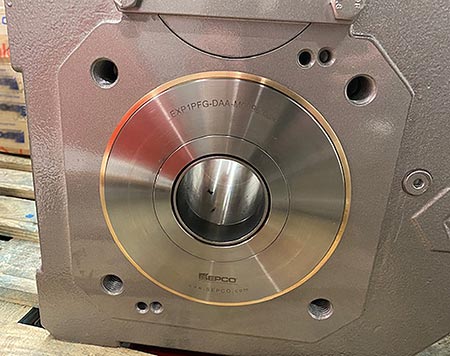
After research, the facility’s reliability engineer chose a noncontact, labyrinth bearing isolator specifically designed for the paper plate punching system (see Image 5). With noncontact, compound labyrinth bearing isolators, oil changes because of contamination may be minimized and, in some cases, eliminated. The design forces contaminants out of the seal with centrifugal force. They are moved away from the bearing and lubricant and out of the gearbox.
Each gearbox at the plant requires two bearing isolators, and the pilot installation eliminated the gearbox leakage on the first of the facility’s 68 gearboxes. Because of this success and since initial installation, the team has replaced the lip seals on about 20 gearboxes and planned to replace the remaining 48 by the end of 2020.